Infiniti FX35 / FX45. Manual — part 873
PS-34
< SERVICE INFORMATION >
POWER STEERING OIL PUMP
6.
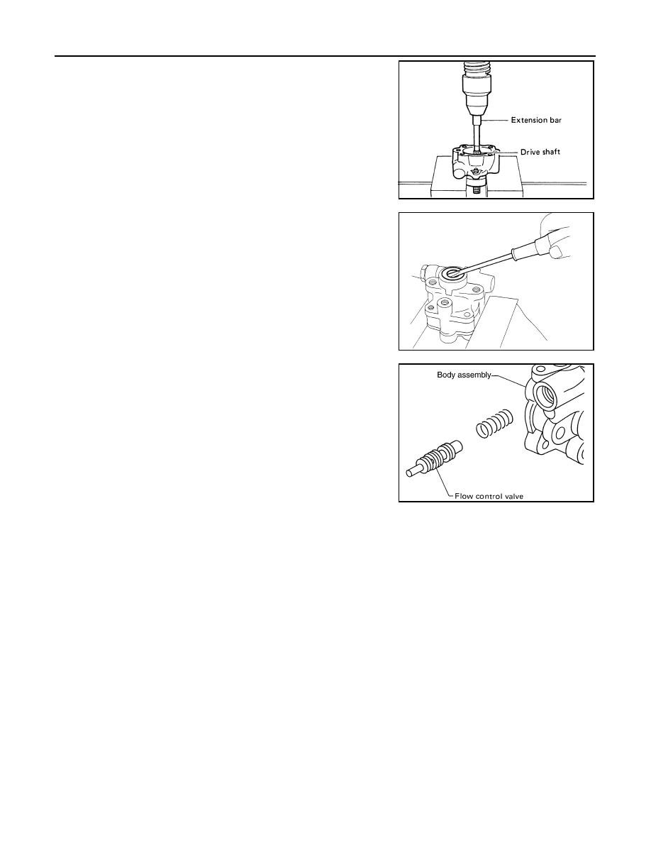
Remove snap ring from drive shaft assembly and press out it.
CAUTION:
When removing snap ring, be careful not to damage drive
shaft assembly.
7.
Using a screwdriver, remove oil seal for body assembly.
8.
Remove O-ring from body assembly.
9.
Loosen lock nut and remove washer, O-ring, joint then remove
connector bolt, O-ring and pull out flow control valve and spring
from body assembly.
CAUTION:
Be careful not to drop and deform the flow control valve.
10. Remove suction pipe from body assembly.
11. Remove O-ring for suction pipe.
INSPECTION AFTER DISASSEMBLY
Body Assembly and Rear Cover Inspection
Check body assembly and rear cover for internal damage. Replace rear cover if it is damaged. Replace oil
pump assembly if body assembly is damaged.
Cartridge Assembly Inspection
Check cam ring, rotor and vane for damage. Replace cartridge assembly if there are.
Side Plate Inspection
Check side plate for damage. Replace side plate if there are.
Flow Control Valve Inspection
Check flow control valve and spring for damage. Replace if there are.
ASSEMBLY
NOTE:
Fix oil pump in vise as vise occasion demands.
CAUTION:
When retaining drive shaft assembly in a vise, always use copper or aluminum plates between vise
and shaft.
SST010B
SST034A
SGIA0524E
POWER STEERING OIL PUMP
PS-35
< SERVICE INFORMATION >
C
D
E
F
H
I
J
K
L
M
A
B
PS
N
O
P
1.
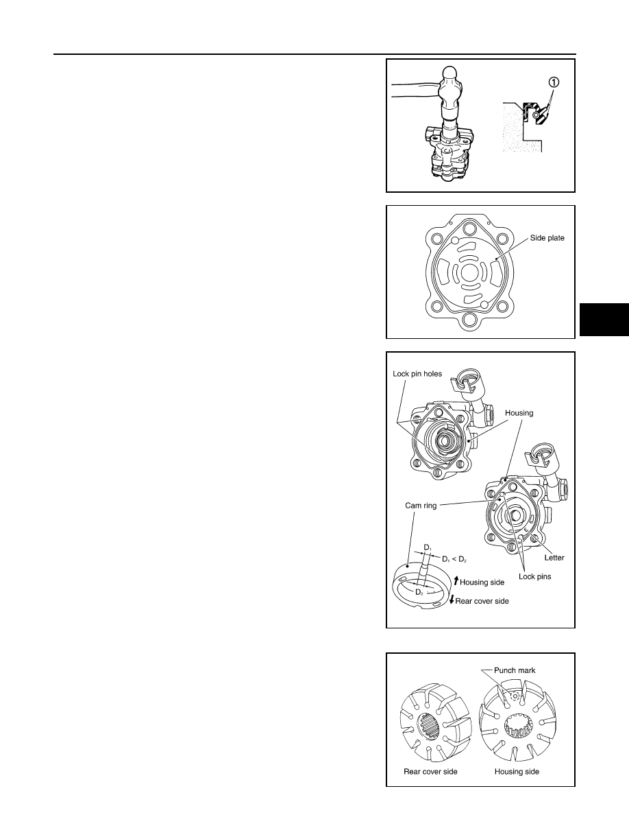
Apply recommended grease to oil seal lips (1). Apply recom-
mended fluid to around oil seal, and then install oil seal to body
assembly.
2.
Apply recommended fluid to drive shaft assembly and press
drive shaft assembly into body assembly with suitable tool, then
install snap ring.
3.
Apply recommended fluid to O-ring and Install O-ring into body
assembly.
4.
Install side plate to body assembly.
5.
Install lock pin into lock pin hole, and install cam-ring as shown
in the figure.
• When installing cam-ring, turn carved face with a letter (E) of it
to rear cover.
CAUTION:
Do not confuse the assembling direction of cam ring. If
cam ring is installed facing the incorrect direction, it may
cause pump operation malfunction.
6.
Install rotor to body assembly.
• When installing rotor, turn punch mark face on rotor to body
assembly.
SGIA1150E
SGIA0422E
SGIA0591E
SGIA0424E
PS-36
< SERVICE INFORMATION >
POWER STEERING OIL PUMP
7.
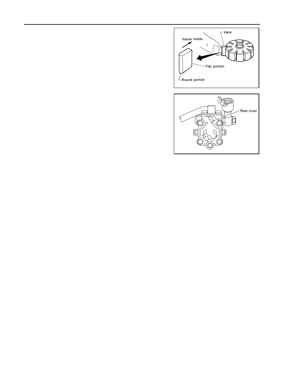
Install vane to rotor with facing the round portion outside.
8.
Check if drive shaft assembly turns smoothly.
9.
Install gasket to body assembly.
10. Install rear cover to body assembly and tighten bolts at the spec-
ified torque.
11. Install bracket to rear cover and tighten bolts at the specified
torque.
12. Install pulley to drive shaft assembly then tighten lock nut at the
specified torque.
13. Install spring, flow control valve, O-ring, connector bolt, joint,
washer to body assembly. Then tighten lock nut at the specified
torque.
14. Apply recommended fluid to O-ring and Install O-ring to suction
pipe.
15. Install suction pipe to body assembly.
SST843A
SGIA0425E
HYDRAULIC LINE
PS-37
< SERVICE INFORMATION >
C
D
E
F
H
I
J
K
L
M
A
B
PS
N
O
P
HYDRAULIC LINE
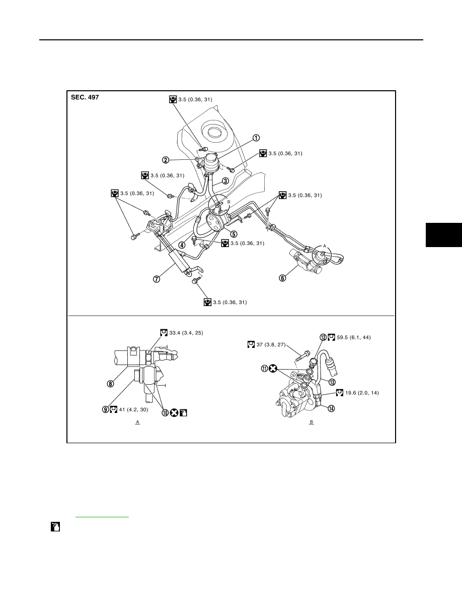
Component
INFOID:0000000001327723
VQ35DE 2WD MODEL
JSGIA0218GB
1.
Reservoir tank
2.
Reservoir tank bracket
3.
Suction hose
4.
High pressure hose
5.
Power steering oil pump
6.
Steering gear assembly
7.
Oil cooler
8.
Clamp
9.
Eye bolt
10. Copper washer
11.
Copper washer
12. Eye bolt
13. Eye joint (assembled to high pres-
sure side hose)
14. Pressure sensor
Refer to
and the followings for the symbols in the figure.
: Apply power steering fluid.
Нет комментариевНе стесняйтесь поделиться с нами вашим ценным мнением.
Текст