Infiniti FX35 / FX45. Manual — part 281
CO-54
< SERVICE INFORMATION >
[VK45DE]
THERMOSTAT AND WATER CONTROL VALVE
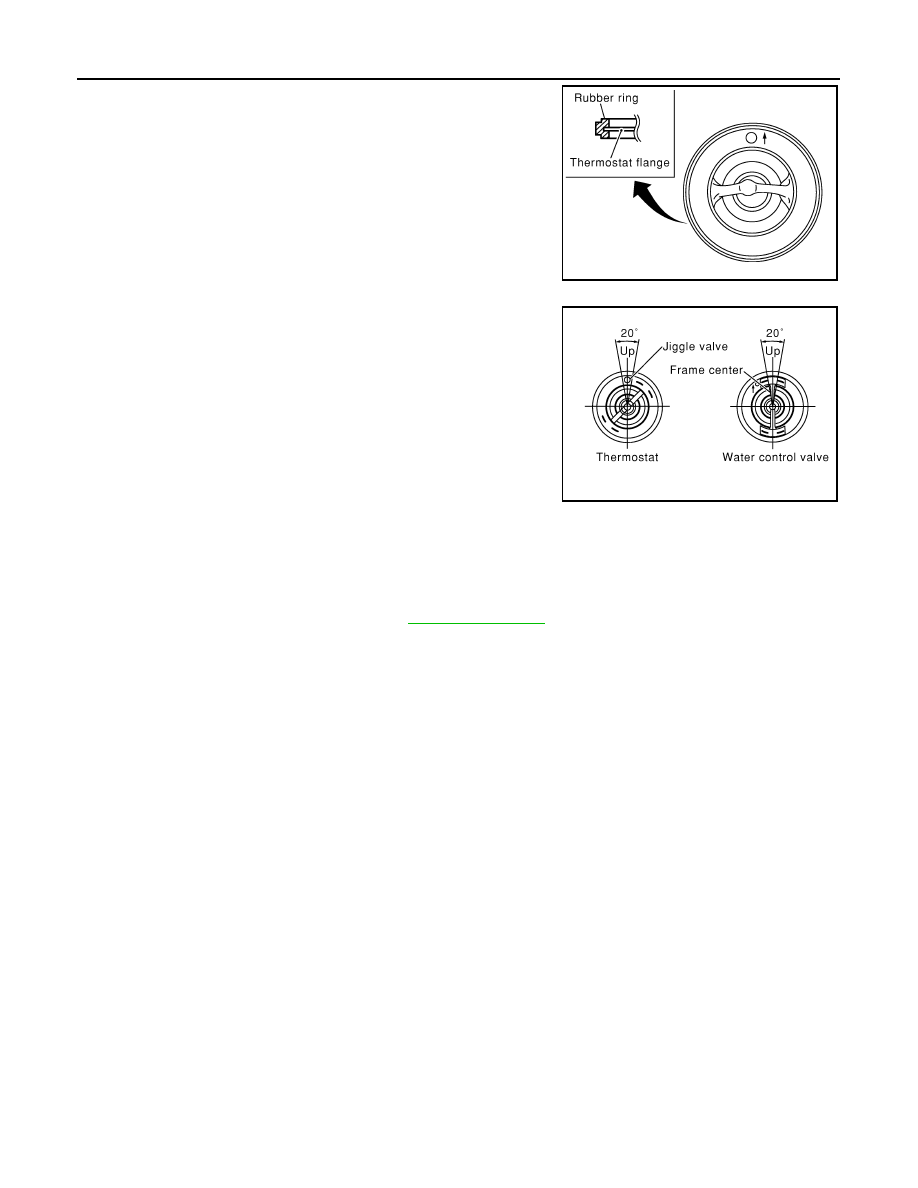
• Install thermostat and water control valve with the whole circumfer-
ence of each flange part fit securely inside rubber ring. (The exam-
ple in the figure shows thermostat.)
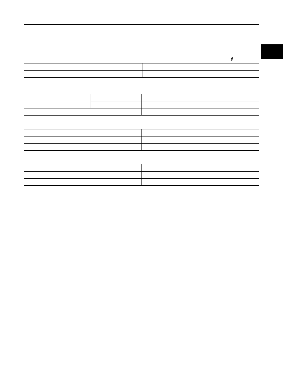
• Install thermostat with jiggle valve facing upwards. (The position
deviation may be within the range of
±
10 degrees)
• Install water control valve with the up-mark facing up and the frame
center part facing upwards. (The position deviation may be within
the range of
±
10 degrees)
Water Outlet Pipe and Heater Pipe
First apply a neutral detergent to O-rings, then quickly insert the insertion parts of the water outlet pipe and
heater pipe into the installation holes.
INSPECTION AFTER INSTALLATION
• Check for leaks of engine coolant using radiator cap tester adapter (commercial service tool) and radiator
cap tester (commercial service tool). Refer to
.
• Start and warm up engine. Visually check if there is no leaks of engine coolant.
PBIC0157E
PBIC0158E
SERVICE DATA AND SPECIFICATIONS (SDS)
CO-55
< SERVICE INFORMATION >
[VK45DE]
C
D
E
F
G
H
I
J
K
L
M
A
CO
N
P
O
SERVICE DATA AND SPECIFICATIONS (SDS)
Standard and Limit
INFOID:0000000001325886
ENGINE COOLANT CAPACITY (APPROXIMATE)
Unit:
(US qt, Imp qt)
RADIATOR
Unit: kPa (kg/cm
2
, psi)
THERMOSTAT
WATER CONTROL VALVE
Engine coolant capacity [With reservoir tank at (“MAX” level)]
10.0 (10-5/8, 8-3/4)
Reservoir tank engine coolant capacity (at “MAX” level)
0.8 (7/8, 3/4)
Radiator cap relief pressure
Standard
78 - 98 (0.8 - 1.0, 11 - 14)
Limit
59 (0.6, 9)
Leakage testing pressure
157 (1.6, 23)
Valve opening temperature
80 - 84
°
C (176 - 183
°
F)
Maximum valve lift
More than 10 mm/95
°
C (0.39 in/203
°
F)
Valve closing temperature
77
°
C (171
°
F)
Valve opening temperature
93.5 - 96.5
°
C (200 - 206
°
F)
Maximum valve lift
More than 8 mm/108
°
C (0.315 in/226
°
F)
Valve closing temperature
90
°
C (194
°
F)
DI-1
ELECTRICAL
C
D
E
F
G
H
I
J
L
M
SECTION
DI
A
B
DI
N
O
P
CONTENTS
DRIVER INFORMATION SYSTEM
SERVICE INFORMATION . . . . . . .
DTC INDEX . . . . . . . . . . . . . . ..
U1000 - U1010 . . . . . . . . . . . . . . ..
B2202 - B2205 . . . . . . . . . . . . . . ..
C1B00 - C1B03 . . . . . . . . . . . . . .....
PRECAUTION . . . . . . . . . . . . . .
COMBINATION METERS . . . . . . . . ...
System Description . . . . . . . . . . . . ...
Component Parts and Harness Connector Loca-
tion . . . . . . . . . . . . . . . . . . ....
Arrangement of Combination Meter . . . . . . ..
Circuit Diagram . . . . . . . . . . . . . ...
Wiring Diagram - METER - . . . . . . . . . .
Terminal and Reference Value for Combination
Meter . . . . . . . . . . . . . . . . . ...
Terminal and Reference Value for Unified Meter
and A/C Amp . . . . . . . . . . . . . . ...
Self-Diagnosis Mode of Combination Meter . . .
CONSULT-III Function (METER/M&A) . . . . ...
Trouble Diagnosis . . . . . . . . . . . . ...
Symptom Chart . . . . . . . . . . . . . ...
Power Supply and Ground Circuit Inspection . . .
Vehicle Speed Signal Inspection . . . . . . . .
Engine Speed Signal Inspection . . . . . . . .
Engine Coolant Temperature Signal Inspection . ..
Fuel Level Sensor Signal Inspection . . . . . ...
Fuel Gauge Pointer Fluctuates, Indicator Wrong
Value or Varies . . . . . . . . . . . . . .
Fuel Gauge Does Not Move to FULL Position . .
Odo/Trip Meter and Illumination Control Switch In-
spection . . . . . . . . . . . . . . . . ...
Electrical Component Inspection . . . . . . . .
Removal and Installation of Combination Meter . .
Disassembly and Assembly of Combination Meter
.
Removal and Installation of Odo/Trip Meter and Il-
lumination Control Switch . . . . . . . . . .
UNIFIED METER AND A/C AMP . . . . . ..
System Description . . . . . . . . . . . . ..
Schematic . . . . . . . . . . . . . . . .
CONSULT-III Function (METER/M&A) . . . . .
Power Supply and Ground Circuit Inspection . . ..
DTC [U1000] CAN Communication Circuit . . . ..
DTC [B2202] Meter Communication Circuit . . .
DTC [B2205] Vehicle Speed Circuit . . . . . .
Removal and Installation of Unified Meter and A/C
Amp . . . . . . . . . . . . . . . . . . .
WARNING LAMPS . . . . . . . . . . .
System Description . . . . . . . . . . . . ..
Schematic . . . . . . . . . . . . . . . .
Wiring Diagram - WARN - . . . . . . . . . ...
Oil Pressure Warning Lamp Stays Off (Ignition
Switch ON) . . . . . . . . . . . . . . . ..
Oil Pressure Warning Lamp Does Not Turn Off
(Oil Pressure Is Normal) . . . . . . . . . . ..
Component Inspection . . . . . . . . . . . .
A/T INDICATOR . . . . . . . . . . . .
System Description . . . . . . . . . . . . ..
Wiring Diagram - AT/IND - . . . . . . . . . ...
A/T Indicator Is Malfunction . . . . . . . . . .
WARNING CHIME . . . . . . . . . . . .
System Description . . . . . . . . . . . . ..
Component Parts and Harness Connector Loca-
tion . . . . . . . . . . . . . . . . . . ...
Schematic . . . . . . . . . . . . . . . .
Wiring Diagram - CHIME - . . . . . . . . . ...
Terminal and Reference Value for BCM . . . . ..
Terminal and Reference Value for Unified Meter
and A/C Amp. . . . . . . . . . . . . . . ..
Terminal and Reference Value for Combination
Meter . . . . . . . . . . . . . . . . . ...
DI-2
CONSULT-III Function (BCM) . . . . . . . ....
Trouble Diagnosis . . . . . . . . . . . . ...
Symptom Chart . . . . . . . . . . . . . ...
Power Supply and Ground Circuit Inspection . . .
Combination Meter Buzzer Circuit Inspection . . .
Front Door Switch (Driver Side) Signal Inspection ...
Key Switch Signal Inspection (Without Intelligent
Key) . . . . . . . . . . . . . . . . . ....
Lighting Switch Signal Inspection . . . . . . ...
Seat Belt Buckle Switch (Driver Side) Signal In-
spection . . . . . . . . . . . . . . . . ..
Component Inspection . . . . . . . . . . ....
LANE DEPARTURE WARNING SYSTEM . .
Precaution for Lane Departure Warning (LDW)
system . . . . . . . . . . . . . . . . ....
System Description . . . . . . . . . . . . .
Action Test . . . . . . . . . . . . . . . ..
Camera Aiming Adjustment . . . . . . . . ....
Component Parts and Harness Connector Loca-
tion . . . . . . . . . . . . . . . . . . ..
Schematic . . . . . . . . . . . . . . . ...
Wiring Diagram - LDW - . . . . . . . . . . .
Terminal and Reference Value for LDW Camera
Unit . . . . . . . . . . . . . . . . . . .
CONSULT-III Function (LDW) . . . . . . . ....
Trouble Diagnosis . . . . . . . . . . . . ...
Preliminary Check . . . . . . . . . . . . ..
Power Supply and Ground Circuit Inspection . . .
DTC [C1B00] CAMERA UNIT MALF . . . . . ..
DTC [C1B01] CAM AIMING INCMP . . . . . ...
DTC [C1B02] VHCL SPD DATA MALF . . . . ..
DTC [C1B03] ABNRML TEMP DETECT . . . ....
DTC [U1000] CAN COMM CIRCUIT . . . . . ..
DTC [U1010] CONTROL UNIT (CAN) . . . . ....
LDW Chime Circuit Inspection . . . . . . . ....
LDW Switch Circuit Inspection . . . . . . . ...
LDW Indicator Lamp Circuit Inspection . . . . ..
Turn Signal Input Inspection . . . . . . . . ...
Electrical Component Inspection . . . . . . .
Removal and Installation for LDW Camera Unit . .
Removal and Installation for LDW Chime . . . ...
Removal and Installation for LDW Switch . . . ...
CAN COMMUNICATION . . . . . . . . ...
System Description . . . . . . . . . . . . .
CAN Communication Unit . . . . . . . . . ...
COMPASS . . . . . . . . . . . . . . .
Precaution for Compass . . . . . . . . . . .
System Description . . . . . . . . . . . . .
Troubleshooting . . . . . . . . . . . . . ..
Zone Variation Setting Procedure . . . . . . ...
Calibration Procedure . . . . . . . . . . . .
Wiring Diagram - COMPAS - . . . . . . . . ..
Removal and Installation of Compass . . . . .
CLOCK . . . . . . . . . . . . . . . ..
Wiring Diagram - CLOCK - . . . . . . . . . .
Removal and Installation of Clock . . . . . . ...
REAR VIEW MONITOR . . . . . . . . .
System Description . . . . . . . . . . . ...
Component Parts and Harness Connector Loca-
tion . . . . . . . . . . . . . . . . . .
Schematic . . . . . . . . . . . . . . . .
Wiring Diagram - R/VIEW - . . . . . . . . ...
Terminal and Reference Value for Rear View
Camera Control Unit . . . . . . . . . . . .
CONSULT-III Function (REARVIEW CAMERA) ...
Side Distance Guideline Correction . . . . . ..
Power Supply and Ground Circuit Inspection . ...
Rear View Is Not Displayed with the A/T Selector
Lever in R-Position . . . . . . . . . . . .
The Rear View Image Is Distorted . . . . . .
Removal and Installation of Rear View Camera
Control Unit . . . . . . . . . . . . . . ...
Нет комментариевНе стесняйтесь поделиться с нами вашим ценным мнением.
Текст