Infiniti FX35 / FX45. Manual — part 280
CO-50
< SERVICE INFORMATION >
[VK45DE]
WATER PUMP
WATER PUMP
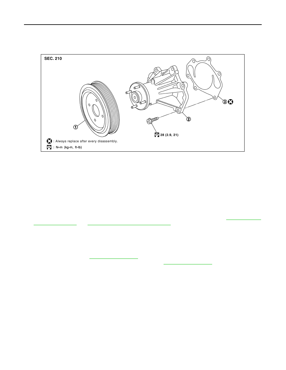
Component
INFOID:0000000001325882
Removal and Installation
INFOID:0000000001325883
CAUTION:
• When removing water pump, be careful not to get engine coolant on drive belts.
• Water pump can not be disassembled and should be replaced as a unit.
• After installing water pump, connect hose and clamp securely, then check for leaks using radiator
cap tester (commercial service tool) and radiator cap tester adapter (commercial service tool).
REMOVAL
1.
Drain engine coolant from drain plugs on radiator and both side of cylinder block. Refer to
EM-242, "Disassembly and Assembly"
CAUTION:
• Perform this step when engine is cold.
• Do not spill engine coolant on drive belts.
2.
Remove following parts:
• Engine front undercover
• Air duct (inlet): Refer to
• Alternator, water pump and A/C compressor belt: Refer to
3.
Remove fan coupling with cooling fan, and then fan and water pump pulley.
4.
Remove water pump.
• Engine coolant will leak from cylinder block, so have a receptacle ready under vehicle.
CAUTION:
• Handle the water pump vane so that it does not contact any other parts.
• Do not disassemble water pump.
INSPECTION AFTER REMOVAL
1.
Fan and water pump pulley
2.
Water pump
3.
Gasket
PBIC1538E
WATER PUMP
CO-51
< SERVICE INFORMATION >
[VK45DE]
C
D
E
F
G
H
I
J
K
L
M
A
CO
N
P
O
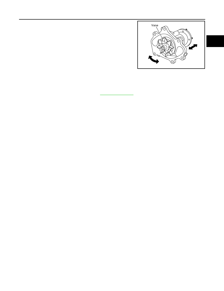
• Visually check that there is no significant dirt or rusting on water
pump body and vane.
• Make sure there is no looseness in vane shaft, and that it turns
smoothly when rotated by hand.
• If anything is found, replace water pump.
INSTALLATION
Install in the reverse order of removal.
INSPECTION AFTER INSTALLATION
• Check for leaks of engine coolant using radiator cap tester adapter (commercial service tool) and radiator
cap tester (commercial service tool). Refer to
.
• Start and warm up engine. Visually check if there is no leaks of engine coolant.
PBIC1539E
CO-52
< SERVICE INFORMATION >
[VK45DE]
THERMOSTAT AND WATER CONTROL VALVE
THERMOSTAT AND WATER CONTROL VALVE
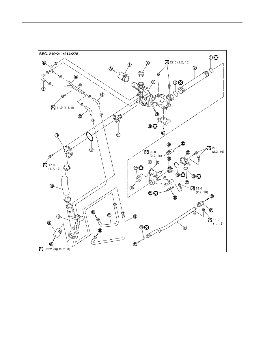
Component
INFOID:0000000001325884
1.
O-ring
2.
Water outlet pipe
3.
Thermostat housing
4.
Radiator cap
5.
Radiator hose (upper)
6.
Water hose
7.
Water hose
8.
Water pipe
9.
Water hose
10.
Water hose
11.
Thermostat
12.
Rubber ring
13.
Water inlet
14.
Water suction hose
15.
Water suction pipe
16.
Radiator hose (lower)
17.
Water hose
18.
Water hose
19.
O-ring
20.
Heater pipe
21.
Heater hose
22.
Gasket
23.
Water outlet
24.
Water control valve
25.
Rubber ring
26.
O-ring
27.
Water connector
28.
Heater hose
29.
Gasket
A.
To radiator
B.
To oil cooler
C.
To cylinder block
PBIC4557E
THERMOSTAT AND WATER CONTROL VALVE
CO-53
< SERVICE INFORMATION >
[VK45DE]
C
D
E
F
G
H
I
J
K
L
M
A
CO
N
P
O
• Refer to
Removal and Installation
INFOID:0000000001325885
REMOVAL
1.
Drain engine coolant from drain plugs on radiator and both side of cylinder block. Refer to
EM-242, "Disassembly and Assembly"
CAUTION:
• Perform this step when engine is cold.
• Do not spill engine coolant on drive belts.
2.
Remove engine cover with power tool. Refer to
3.
Remove air duct (inlet). Refer to
4.
Disconnect water suction hose from water inlet.
5.
Remove water inlet and thermostat.
CAUTION:
Do not disassemble thermostat.
6.
Remove intake manifolds (upper and lower). Refer to
.
7.
Disconnect radiator hose (upper) and water hoses from thermostat housing.
8.
Disconnect heater hoses from water outlet and heater pipe.
9.
Remove thermostat housing, water outlet pipe, water connector, water control valve, water outlet and
heater pipe.
CAUTION:
Do not disassemble water control valve.
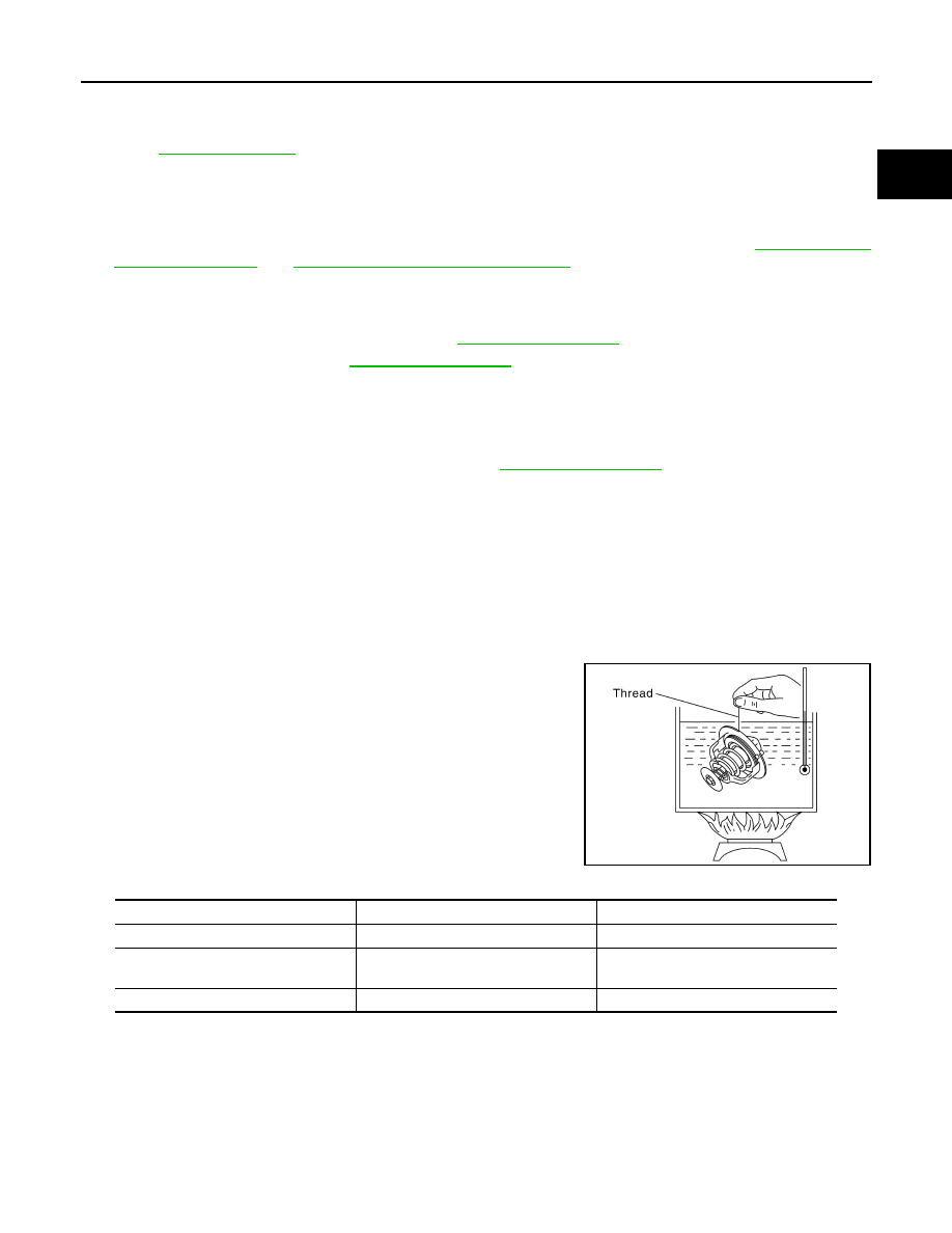
INSPECTION AFTER REMOVAL
• Make sure that valves both in thermostat and water control valve are completely closing at normal tempera-
ture.
• Place a thread so that it is caught in the valves of the thermostat
and water control valve. Immerse fully in a container filled with
water. Heat while stirring. (The example in the figure shows ther-
mostat.)
• The valve opening temperature is the temperature at which the
valve opens and falls from the thread.
• Continue heating. Check the maximum valve lift.
NOTE:
The maximum valve lift standard temperature for water control
valve is the reference value.
• After checking the maximum valve lift, lower the water tempera-
ture and check the valve closing temperature.
Standard values:
• If the malfunctioning condition, when closing valve at normal temperature, or measured values are out of the
standard, replace thermostat and/or water control valve.
INSTALLATION
Note the following, and install in the reverse order of removal.
CAUTION:
Be careful not to spill engine coolant over engine room. Use rag to absorb engine coolant.
Thermostat and Water Control Valve
D.
To heater core
E.
To cylinder head (left bank)
F.
To cylinder head (right bank)
G.
To intake manifold adapter
SLC252B
Thermostat
Water control valve
Valve opening temperature
80 - 84
°
C (176 - 183
°
F)
93.5 - 96.5
°
C (200 - 206
°
F)
Maximum valve lift
More than 10 mm/95
°
C
(0.39 in/203
°
F)
More than 8 mm/108
°
C
(0.315 in/226
°
F)
Valve closing temperature
77
°
C (171
°
F)
90
°
C (194
°
F)
Нет комментариевНе стесняйтесь поделиться с нами вашим ценным мнением.
Текст