Infiniti FX35 / FX45. Manual — part 921

SE-42
< SERVICE INFORMATION >
AUTOMATIC DRIVE POSITIONER
ACTIVE TEST
CAUTION:
During vehicle driving, do not perform active test.
NOTE:
If active test is performed, reset seat memory and key fob interlock drive positioner after performing work.
Display Item List
Check CAN Communication System
INFOID:0000000001532368
1.
PERFORM SELF DIAGNOSTIC
1.
Turn ignition switch ON and wait for 2 seconds or more.
2.
Check “Self Diagnostic Result” of BCM.
TILT SW-UP
“ON/OFF”
ON/OFF status judged from the tilt switch (UP) signal is displayed.
TILT SW-DOWN
“ON/OFF”
ON/OFF status judged from the tilt switch (DOWN) signal is displayed.
SET SW
“ON/OFF”
ON/OFF status judged from the setting switch signal is displayed.
MEMORY SW1
“ON/OFF”
ON/OFF status judged from the seat memory switch 1 signal is displayed.
MEMORY SW2
“ON/OFF”
ON/OFF status judged from the seat memory switch 2 signal is displayed.
P POSI SW
“ON/OFF”
The selector lever position “ON (P position) / OFF (other than P position)” judged
from the park position switch signal is displayed.
STARTER SW
“ON/OFF”
Ignition key switch ON (START, ON) /OFF (ignition switch IGN, ACC, or OFF) sta-
tus judged from the ignition switch signal is displayed.
SLIDE PULSE
—
Value (32768) when battery connects is as standard. If it moves backward, the val-
ue increases. If it moves forward, the value decreases.
RECLN RULSE
—
Value (32768) when battery connects is as standard. If it moves backward, the val-
ue increases. If it moves forward, the value decreases.
LIFT FR PULSE
—
Value (32768) when battery connects is as standard. If it moves DOWN, the value
increases. If it moves UP, the value decreases.
LIFT RR PULSE
—
Value (32768) when battery connects is as standard. If it moves DOWN, the value
increases. If it moves UP, the value decreases.
TILT SEN
“V”
The tilt position (voltage) judged from the tilt sensor signal is displayed.
TELESCO SEN
“V”
The telescoping position (voltage) judged from the telescoping sensor signal is dis-
played.
MIR/SE RH R–L
“V”
Voltage output from RH door mirror sensor (LH/RH) is displayed.
MIR/SE RH U–D
“V”
Voltage output from RH door mirror sensor (UP/DOWN) is displayed.
MIR/SE LH R–L
“V”
Voltage output from LH door mirror sensor (LH/RH) is displayed.
MIR/SE LH U–D
“V”
Voltage output from LH door mirror sensor (UP/DOWN) is displayed.
Monitor item [OPERATION or UNIT]
Contents
Test item
Description
TILT MOTOR
The tilt motor is activated by receiving the drive signal.
TELESCO MOTOR
The telescopic motor is activated by receiving the drive signal.
SEAT SLIDE
The sliding motor is activated by receiving the drive signal.
SEAT RECLINING
The reclining motor is activated by receiving the drive signal.
SEAT LIFTER FR
The front end lifter motor is activated by receiving the drive signal.
SEAT LIFTER RR
The rear end lifter motor is activated by receiving the drive signal.
MEMORY SW INDCTR
The memory switch indicator is lit by receiving the drive signal.
MIRROR MOTOR RH
The RH mirror motor moves the mirror UP/DOWN and LEFT/RIGHT by receiving the drive
signal.
MIRROR MOTOR LH
The LH mirror motor moves the mirror UP/DOWN and LEFT/RIGHT by receiving the drive
signal.

AUTOMATIC DRIVE POSITIONER
SE-43
< SERVICE INFORMATION >
C
D
E
F
G
H
J
K
L
M
A
B
SE
N
O
P
Is “CAN COMM CIRCUIT” displayed?
YES
>> Refer to
LAN-14, "Trouble Diagnosis Flow Chart"
NO
>> INSPECTION END.
Symptom Chart
INFOID:0000000001328110
Symptom
Diagnoses / service procedure
Refer to
page
Only setting change function cannot be set with display.
Interacted display system (without NAVI)
Navigation system (with NAVI)
A part of seat system does not operate
(both automatically and manually).
1.
Check sliding motor circuit
2.
Check reclining motor circuit
3.
Check front lifter motor circuit
4.
Check rear lifter motor circuit
5.
If the above systems are normal, replace the driver
seat control unit
A part of steering tilt, telescopic and door mirror does not
operate (both automatically and manually).
1.
Check tilt motor circuit
2.
Check telescopic motor circuit
3.
Check driver side mirror motor circuit
4.
Check passenger side mirror motor circuit
5.
If the above systems are normal, replace the
automatic drive positioner control unit
A part of seat system does not operate
(only automatic operation).
1.
Check sliding sensor circuit
2.
Check reclining sensor circuit
3.
Check front lifting sensor circuit
4.
Check rear lifting sensor circuit
5.
If the above systems are normal, replace the driver
seat control unit
A part of steering tilt, telescopic system and door mirror
system dose not operate (only automatic operation).
1.
Check steering and door mirror sensor power supply
and ground circuit
2.
Check driver side mirror sensor circuit
3.
Check passenger side mirror sensor circuit
4.
Check tilt sensor circuit
5.
Check telescopic sensor circuit
6.
If all the above systems are normal, replace the
automatic drive positioner control unit
All the automatic operations do not operate.
1.
Check A/T device (park position switch) circuit
2.
Check key switch circuit (with intelligent key)
3.
Check key switch circuit (without intelligent key)
4.
Check UART communication line circuit
5.
If all the above systems are normal, replace the
automatic drive positioner control unit
A part of seat system does not operate
(only manual operation).
1.
Check sliding switch circuit
2.
Check reclining switch circuit
3.
Check front lifting switch circuit
4.
Check rear lifting switch circuit
5.
If the above systems are normal, replace the driver
seat control unit
SE-44
< SERVICE INFORMATION >
AUTOMATIC DRIVE POSITIONER
Check Sliding Motor Circuit
INFOID:0000000001328111
1.
CHECK SEAT SLIDING MECHANISM
Check the following.
• Operation malfunction caused by sliding rail deformation or pinched harness or other foreign materials
• Operation malfunction caused by foreign materials adhered to the sliding motor or sliding rail connector rod
• Operation malfunction and interference with other parts by poor installation
OK or NG
OK
>> • GO TO 2 (With CONSULT-III).
• GO TO 3 (Without CONSULT-III).
NG
>> Repair the malfunctioning part and check again.
2.
CHECK FUNCTION
With CONSULT-III
Check operation with “SEAT SLIDE” in ACTIVE TEST.
OK or NG
OK
>> Sliding motor circuit is OK.
NG
>> GO TO 3.
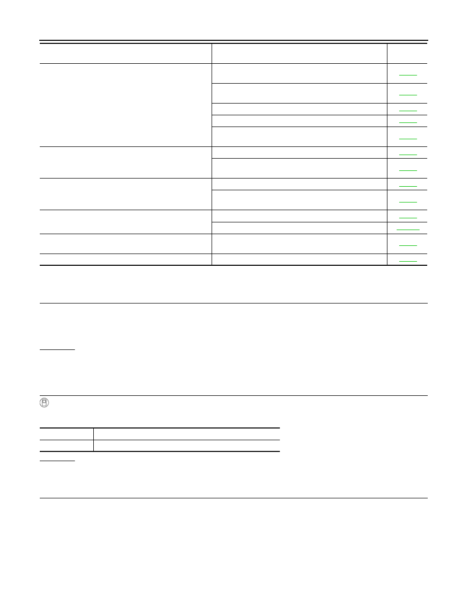
3.
CHECK SLIDING MOTOR HARNESS CONTINUITY
1.
Turn ignition switch OFF.
2.
Disconnect driver seat control unit connector and sliding motor connector.
A part of steering tilt, telescopic and door mirror does not
operate (only manual operation).
1.
Check door mirror remote control switch (changeover
switch) circuit
2.
Check door mirror remote control switch (mirror switch)
circuit
3.
Check tilt switch circuit
4.
Check telescopic switch circuit
5.
If the above systems are normal, replace the
automatic drive positioner control unit
Only seat memory switch operation dose not operate.
1.
Check seat memory switch circuit
2.
If the above systems are normal, replace the driver
seat control unit
Seat memory indicator lamps 1 and 2 do not illuminate.
1.
Check seat memory indicator lamp circuit
2.
If all the above systems are normal, replace the driver
seat control unit
The Entry/Exiting does not operated when door is opened
and closed. (The Entry/Exiting operates with key switch)
1.
Check front door switch (driver side) circuit
2.
If all the above systems are normal, replace the BCM
Only seat sliding, seat reclining and seat lifting (front and
rear) operations do not operate.
Check power seat switch ground circuit
Only lumbar support does not operate.
Check lumbar support circuit
Symptom
Diagnoses / service procedure
Refer to
page
Test item
Description
SEAT SLIDE
The sliding motor is activated by receiving the drive signal.
AUTOMATIC DRIVE POSITIONER
SE-45
< SERVICE INFORMATION >
C
D
E
F
G
H
J
K
L
M
A
B
SE
N
O
P
3.
Check continuity between driver seat control unit connector
B153 terminals 3, 10 and sliding motor connector B161 termi-
nals 3, 10.
4.
Check continuity between driver seat control unit connector
B153 terminals 3, 10 and ground.
OK or NG
OK
>> GO TO 4.
NG
>> Repair or replace harness between driver seat control unit and sliding motor.
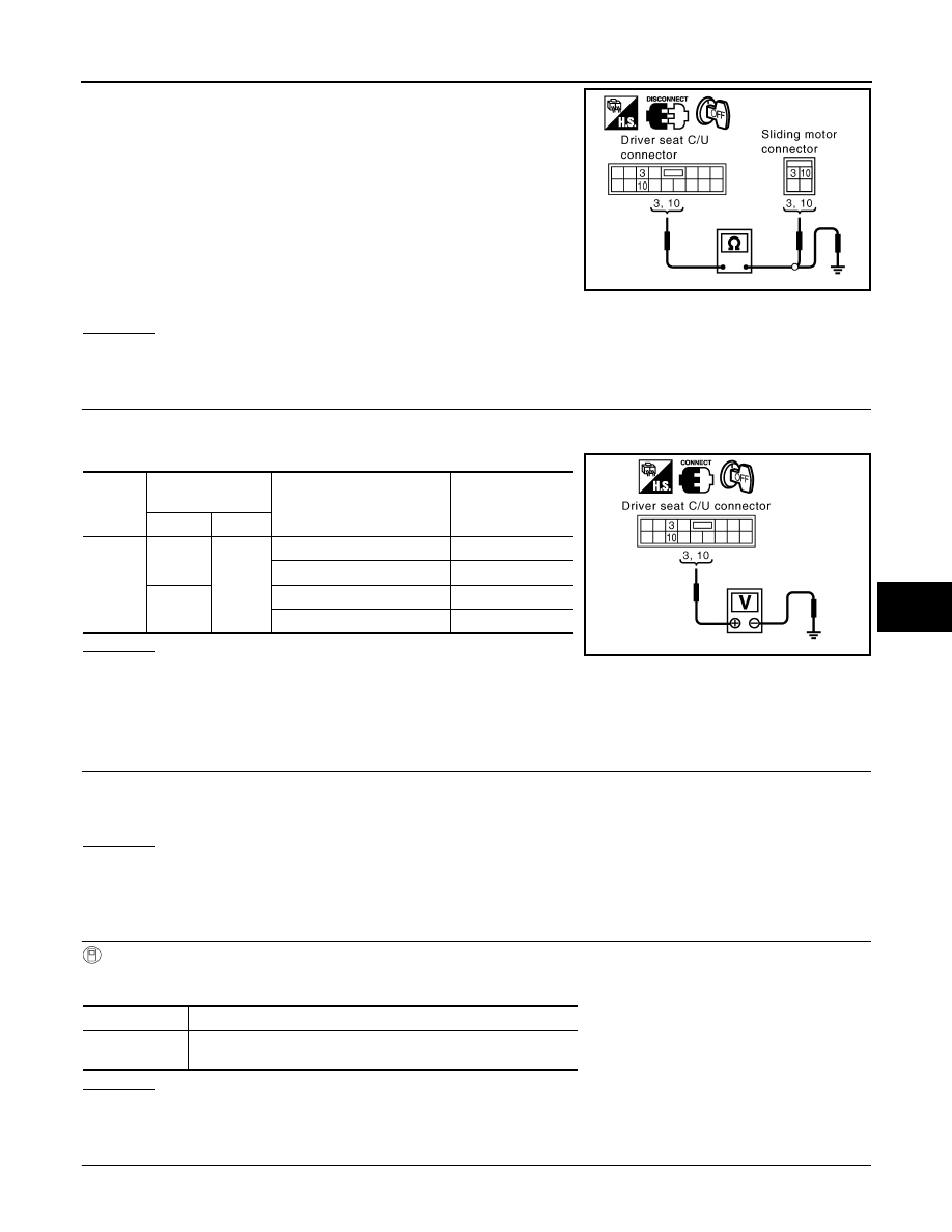
4.
CHECK DRIVER SEAT CONTROL UNIT OUTPUT SIGNAL
1.
Connect the driver seat control unit connector.
2.
Sliding switch operate, check voltage between driver seat control unit connector and ground.
OK or NG
OK
>> Replace sliding motor.
NG
>> Replace driver seat control unit.
Check Reclining Motor Circuit
INFOID:0000000001328112
1.
CHECK SEAT RECLINING MECHANISM
Check the following.
• Operation malfunction caused by an interference with the center pillar or center console
• Operation malfunction and interference with other parts by poor installation
OK or NG
OK
>> • GO TO 2 (With CONSULT-III).
• GO TO 3 (Without CONSULT-III).
NG
>> Repair the malfunctioning part and check again.
2.
CHECK FUNCTION
With CONSULT-III
Check operation with “SEAT RECLINING” in ACTIVE TEST.
OK or NG
OK
>> Reclining motor circuit is OK.
NG
>> GO TO 3.
3.
CHECK RECLINING MOTOR HARNESS CONTINUITY
1.
Turn ignition switch OFF.
3 (G) – 3 (G)
: Continuity should exist.
10 (G/R) – 10 (G/R)
: Continuity should exist.
3 (G) – Ground
: Continuity should not exist.
10 (G/R) – Ground
: Continuity should not exist.
PIIA6114E
Connec-
tor
Terminals
(Wire color)
Sliding switch condition
Voltage (V) (Ap-
prox.)
(+)
(–)
B153
3 (G)
Ground
FORWARD
Battery voltage
Other than above
0
10 (G/R)
BACKWARD
Battery voltage
Other than above
0
PIIA6113E
Test item
Description
SEAT
RECLINING
The reclining motor is activated by receiving the drive signal.
Нет комментариевНе стесняйтесь поделиться с нами вашим ценным мнением.
Текст