Infiniti FX35 / FX45. Manual — part 357
DTC P0112, P0113 IAT SENSOR
EC-189
< SERVICE INFORMATION >
[VQ35DE]
C
D
E
F
G
H
I
J
K
L
M
A
EC
N
P
O
DTC P0112, P0113 IAT SENSOR
Component Description
INFOID:0000000001326006
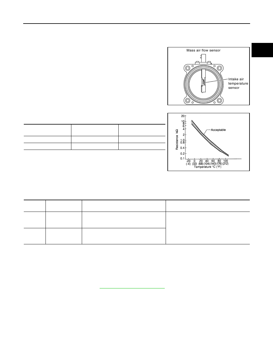
The intake air temperature (IAT) sensor is built-into mass air flow
sensor. The sensor detects intake air temperature and transmits a
signal to the ECM.
The temperature sensing unit uses a thermistor which is sensitive to
the change in temperature. Electrical resistance of the thermistor
decreases in response to the temperature rise.
<Reference data>
*: This data is reference values and is measured between ECM terminal 34 (Intake
air temperature sensor) and ground.
CAUTION:
Do not use ECM ground terminals when measuring input/output
voltage. Doing so may result in damage to the ECM's transistor.
Use a ground other than ECM terminals, such as the ground.
On Board Diagnosis Logic
INFOID:0000000001326007
DTC Confirmation Procedure
INFOID:0000000001326008
NOTE:
If DTC Confirmation Procedure has been previously conducted, always turn ignition switch OFF and wait at
least 10 seconds before conducting the next test.
1.
Turn ignition switch ON and wait at least 5 seconds.
2.
Check 1st trip DTC.
3.
If 1st trip DTC is detected, go to
PBIB1604E
Intake air temperature
°
C (
°
F)
Voltage*
V
Resistance
k
Ω
25 (77)
3.30
1.800 - 2.200
80 (176)
1.22
0.283 - 0.359
SEF012P
DTC No.
Trouble diagnosis
name
DTC detecting condition
Possible cause
P0112
0112
Intake air tempera-
ture sensor circuit
low input
An excessively low voltage from the sensor is
sent to ECM.
• Harness or connectors
(Intake air temperature sensor circuit is open
or shorted.)
• Intake air temperature sensor
P0113
0113
Intake air tempera-
ture sensor circuit
high input
An excessively high voltage from the sensor is
sent to ECM.
EC-190
< SERVICE INFORMATION >
[VQ35DE]
DTC P0112, P0113 IAT SENSOR
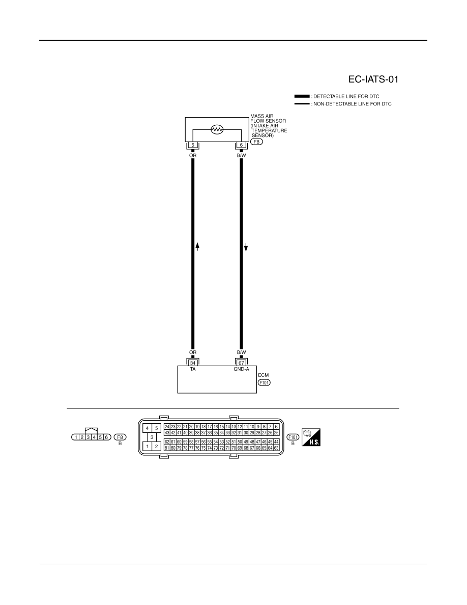
Wiring Diagram
INFOID:0000000001326009
Diagnosis Procedure
INFOID:0000000001326010
1.
CHECK GROUND CONNECTIONS
1.
Turn ignition switch OFF.
TBWM0288E

DTC P0112, P0113 IAT SENSOR
EC-191
< SERVICE INFORMATION >
[VQ35DE]
C
D
E
F
G
H
I
J
K
L
M
A
EC
N
P
O
2.
Loosen and retighten ground screw on the body. Refer to
OK or NG
OK
>> GO TO 2.
NG
>> Repair or replace ground connections.
2.
CHECK INTAKE AIR TEMPERATURE SENSOR POWER SUPPLY CIRCUIT
1.
Disconnect mass air flow sensor (with intake air temperature
sensor) harness connector.
2.
Turn ignition switch ON.
3.
Check voltage between mass air flow sensor terminal 5 and
ground.
OK or NG
OK
>> GO TO 3.
NG
>> Repair harness or connectors.
3.
CHECK INTAKE AIR TEMPERATURE SENSOR GROUND CIRCUIT FOR OPEN AND SHORT
1.
Turn ignition switch OFF.
2.
Disconnect ECM harness connector.
3.
Check harness continuity between mass air flow sensor terminal 6 and ECM terminal 67.
Refer to Wiring Diagram.
4.
Also check harness for short to ground and short to power.
OK or NG
OK
>> GO TO 4.
NG
>> Repair open circuit or short to ground or short to power in harness or connectors.
4.
CHECK INTAKE AIR TEMPERATURE SENSOR
EC-192, "Component Inspection"
OK or NG
OK
>> GO TO 5.
NG
>> Replace mass air flow sensor (with intake air temperature sensor).
PBIB2625E
PBIB1565E
Voltage: Approximately 5V
PBIB1169E
Continuity should exist.
EC-192
< SERVICE INFORMATION >
[VQ35DE]
DTC P0112, P0113 IAT SENSOR
5.
CHECK INTERMITTENT INCIDENT
>> INSPECTION END
Component Inspection
INFOID:0000000001326011
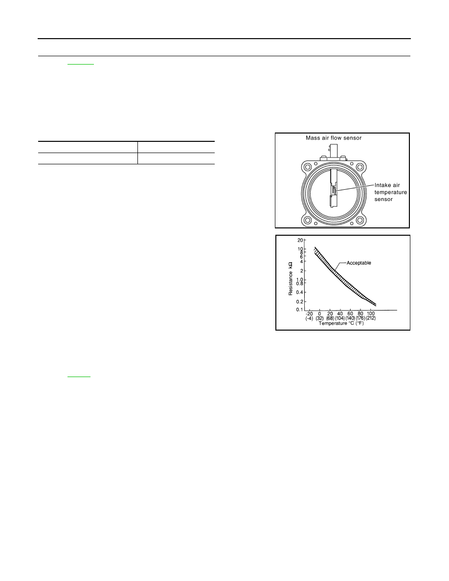
INTAKE AIR TEMPERATURE SENSOR
Check resistance between mass air flow sensor terminals 5 and 6 under the following conditions.
If NG, replace mass air flow sensor (with intake air temperature sen-
sor).
Removal and Installation
INFOID:0000000001326012
MASS AIR FLOW SENSOR
Intake air temperature
°
C (
°
F)
Resistance k
Ω
25 (77)
1.800 - 2.200
PBIB1604E
SEF012P
Нет комментариевНе стесняйтесь поделиться с нами вашим ценным мнением.
Текст