Infiniti FX35 / FX45. Manual — part 675
CAMSHAFT
EM-217
< SERVICE INFORMATION >
[VK45DE]
C
D
E
F
G
H
I
J
K
L
M
A
EM
N
P
O
4.
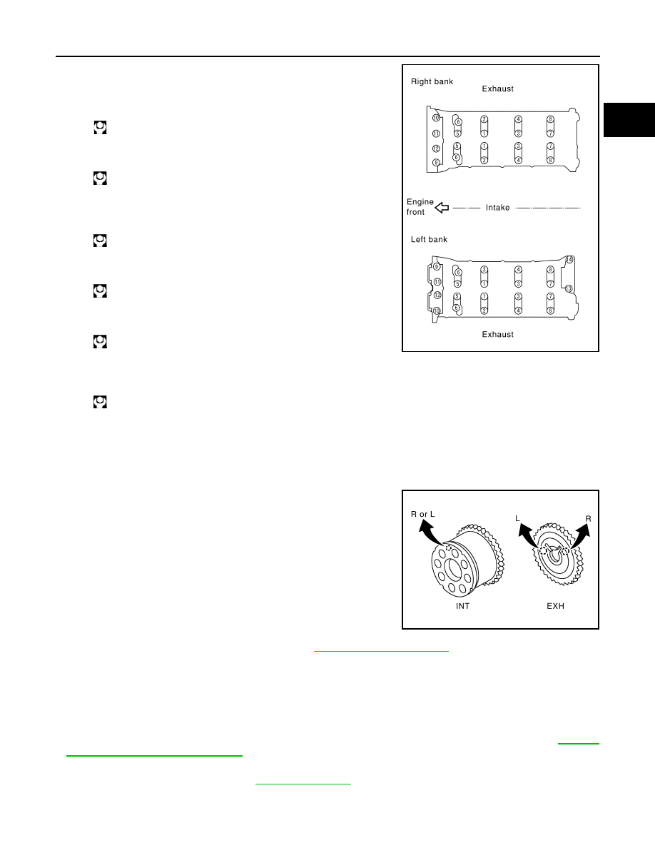
Tighten camshaft bracket bolts in the following steps, in numeri-
cal order as shown in the figure.
a.
Tighten No. 9 to 12 in numerical order as shown.
b.
Tighten No. 1 to 8 in numerical order as shown.
c.
Tighten No. 13 to 14 in numerical order as shown. (Left bank
only)
d.
Tighten all bolts in numerical order as shown.
e.
Tighten No. 1 to 12 in numerical order as shown.
f.
Tighten No. 13 to 14 in numerical order as shown. (Left bank
only)
CAUTION:
After tightening mounting bolts of camshaft brackets, be sure to wipe off excessive liquid gasket
from the parts listed below.
• Mating surface of rocker cover
• Mating surface of front cover
5.
Install camshaft sprockets.
• Install by checking with identification mark on surface.
• Install camshaft sprocket (EXH) by selectively using the
groove of dowel pin according to the bank. (Common part
used for both banks.)
• Lock the hexagonal part of camshaft in the same way as for
removal, and tighten mounting bolts.
6.
Check and adjust the valve clearance. Refer to
7.
Install in the reverse order of removal after this step.
INSPECTION AFTER INSTALLATION
Inspection of Camshaft Sprocket (INT) Oil Groove
CAUTION:
• Perform this inspection only when DTC P0011 and/or P0021 are detected in self-diagnostic results of
CONSULT-III and it is directed according to inspection procedure of EC section. Refer to
"Trouble Diagnosis Introduction"
• Check when the engine is cold so as to prevent burns from any splashing engine oil.
1.
Check the engine oil level. Refer to
2.
Perform the following procedure so as to prevent the engine from being unintentionally started while
checking.
: 1.96 N·m (0.2 kg-m, 1 ft-lb)
: 1.96 N·m (0.2 kg-m, 1 ft-lb)
: 1.96 N·m (0.2 kg-m, 1 ft-lb)
: 5.88 N·m (0.6 kg-m, 4 ft-lb)
: 10.41 N·m (1.1 kg-m, 8 ft-lb)
: 31.35 N·m (3.2 kg-m, 23 ft-lb)
PBIC0031E
PBIC2345E
EM-218
< SERVICE INFORMATION >
[VK45DE]
CAMSHAFT
a.
Release fuel pressure. Refer to
.
b.
Disconnect ignition coil and injector harness connectors.
3.
Remove intake valve timing control solenoid valve. Refer to
.
4.
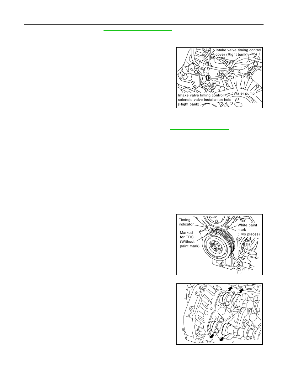
Crank the engine, and then make sure that engine oil comes out
from intake valve timing control cover oil hole. End crank after
checking.
WARNING:
Be careful not to touch rotating parts (drive belt, idler pul-
ley, and crankshaft pulley, etc.).
CAUTION:
Engine oil may squirt from intake valve timing control sole-
noid valve installation hole during cranking. Use a shop
cloth to prevent the engine components and the vehicle. Do
not allow engine oil to get on rubber components such as
drive belt or engine mount insulators. Immediately wipe off
any splashed engine oil.
• Clean oil groove between oil strainer and intake valve timing control solenoid valve if engine oil does not
come out from intake valve timing control cover oil hole. Refer to
.
5.
Remove components between intake valve timing control solenoid valve and camshaft sprocket (INT),
and then check each oil groove for clogging.
• Clean oil groove if necessary. Refer to
.
6.
After inspection, install removed parts.
Valve Clearance
INFOID:0000000001325792
INSPECTION
In cases of removing/installing or replacing camshaft and valve-related parts, or of unusual engine conditions
due to changes in valve clearance (found malfunctions during starting, idling or causing noise), perform
inspection as follows:
1.
Remove rocker covers (right and left bank). Refer to
.
2.
Measure the valve clearance as follows:
a.
Set No. 1 cylinder at TDC of its compression stroke.
• Rotate crankshaft pulley in clockwise to align TDC identifica-
tion notch (without paint mark) with timing indicator on front
cover.
• Make sure that both intake and exhaust cam noses of No. 1
cylinder (engine front side of left bank) are located as shown in
the figure.
• If not, turn crankshaft one revolution (360 degrees) and align
as shown in the figure.
PBIC2848E
PBIC2341E
KBIA0400J
CAMSHAFT
EM-219
< SERVICE INFORMATION >
[VK45DE]
C
D
E
F
G
H
I
J
K
L
M
A
EM
N
P
O
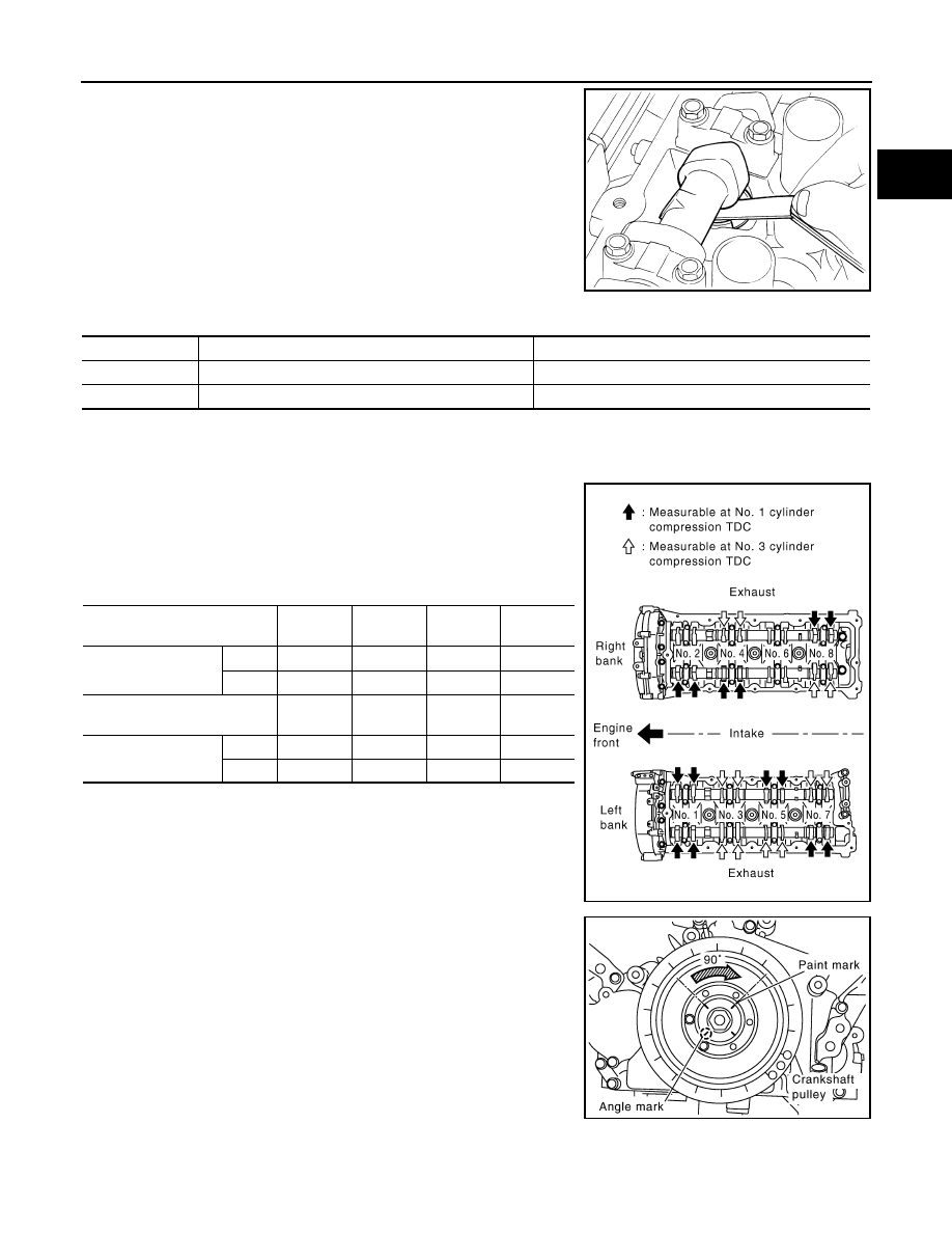
b.
Use feeler gauge, measure the clearance between valve lifter
and camshaft.
Valve clearance:
Unit: mm (in)
*:Approximately 80
°
C (176
°
F)
• By referring to the figure, measure the valve clearances at
locations marked “
×
” as shown in the table below (locations
indicated with black arrow in figure).
NOTE:
Firing order 1-8-7-3-6-5-4-2
• No. 1 cylinder at compression TDC
c.
Rotate crankshaft pulley clockwise (when view from engine
front) by 270 degrees from the position of No. 1 cylinder com-
pression TDC to align No. 3 cylinder at TDC of its compression
stroke.
NOTE:
Crankshaft pulley mounting bolt flange has a angle mark every
90 degrees. They can be used as a guide to rotation angle.
SEM139D
Cold
Hot * (reference data)
Intake
0.26 - 0.34 (0.010 - 0.013)
0.304 - 0.416 (0.012 - 0.016)
Exhaust
0.29 - 0.37 (0.011 - 0.015)
0.308 - 0.432 (0.012 - 0.017)
Measuring position (right bank)
No. 2
CYL.
No. 4
CYL.
No. 6
CYL.
No. 8
CYL.
No. 1 cylinder at com-
pression TDC
EXH
×
INT
×
×
Measuring position (left bank)
No. 1
CYL.
No. 3
CYL.
No. 5
CYL.
No. 7
CYL.
No. 1 cylinder at com-
pression TDC
INT
×
×
EXH
×
×
PBIC2358E
PBIC2346E
EM-220
< SERVICE INFORMATION >
[VK45DE]
CAMSHAFT
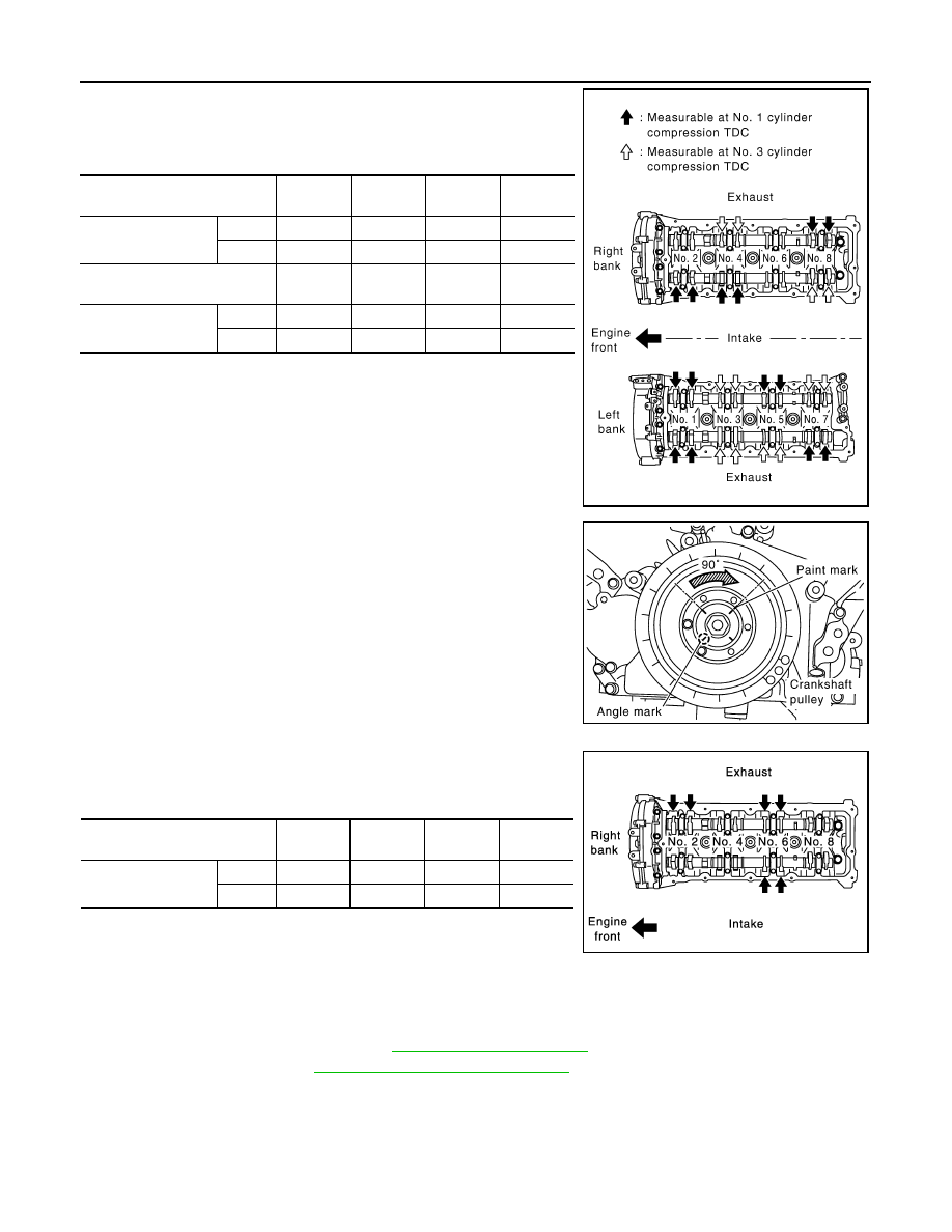
• By referring to the figure, measure the valve clearances at
locations marked “
×
” as shown in the table below (locations
indicated with white arrow in figure).
• No. 3 cylinder at compression TDC
d.
Rotate crankshaft pulley clockwise (when view from engine
front) by 90 degrees from the position of No. 3 cylinder compres-
sion TDC to align No. 6 cylinder at TDC of its compression
stroke.
• By referring to the figure, measure the valve clearances at
locations marked “
×
” as shown in the table below.
• No. 6 cylinder at compression TDC
3.
For the measured value are out of the standard, perform adjustment. Refer to "ADJUSTMENT".
ADJUSTMENT
• Perform adjustment depending on selected head thickness of valve lifter.
1.
Measure the valve clearance. Refer to
2.
Remove camshaft. Refer to
EM-211, "Removal and Installation"
3.
Remove valve lifters at the locations that are out of the standard.
Measuring position (right bank)
No. 2
CYL.
No. 4
CYL.
No. 6
CYL.
No. 8
CYL.
No. 3 cylinder at
compression TDC
EXH
×
INT
×
Measuring position (left bank)
No. 1
CYL.
No. 3
CYL.
No. 5
CYL.
No. 7
CYL.
No. 3 cylinder at
compression TDC
INT
×
×
EXH
×
×
PBIC2358E
PBIC2346E
Measuring position (right bank)
No. 2
CYL.
No. 4
CYL.
No. 6
CYL.
No. 8
CYL.
No. 6 cylinder at
compression TDC
EXH
×
×
INT
×
PBIC0824E
Нет комментариевНе стесняйтесь поделиться с нами вашим ценным мнением.
Текст