Infiniti FX35 / FX45. Manual — part 676
CAMSHAFT
EM-221
< SERVICE INFORMATION >
[VK45DE]
C
D
E
F
G
H
I
J
K
L
M
A
EM
N
P
O
4.
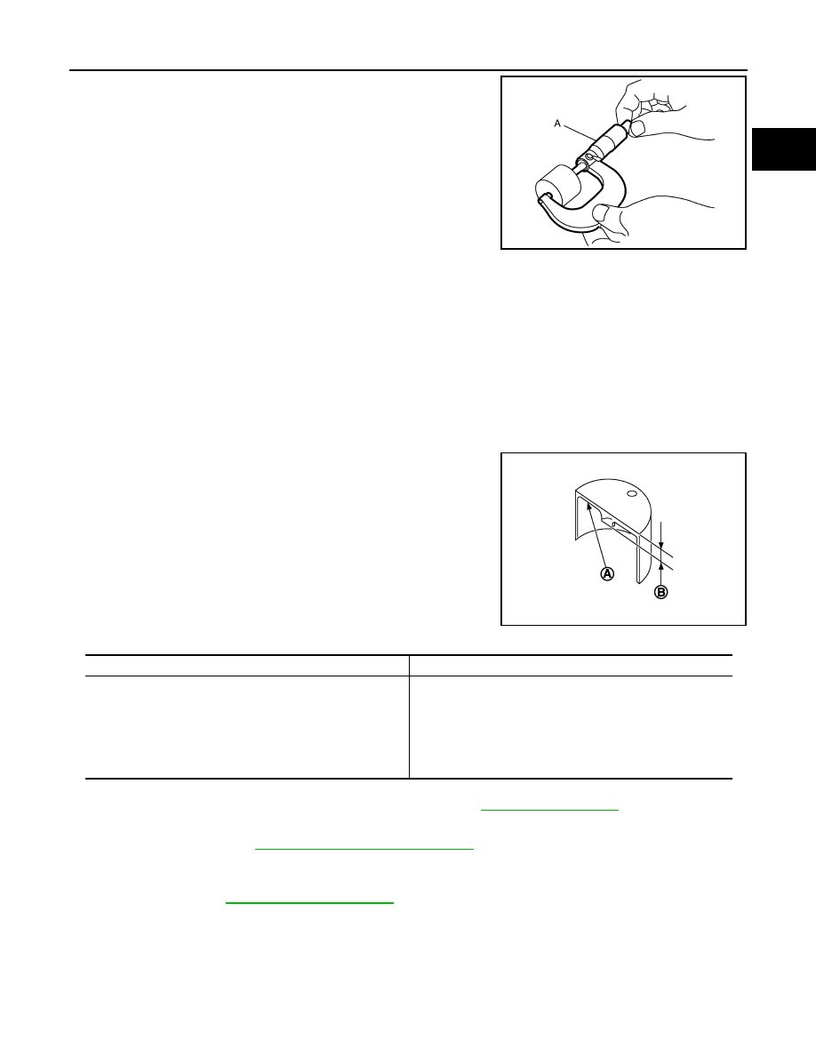
Measure the center thickness of the removed valve lifters with a
micrometer (A).
5.
Use the equation below to calculate valve lifter thickness for replacement.
• Thickness of new valve lifter can be identified by stamp marks
on the reverse side (inside the cylinder).
Stamp mark 788U indicates 7.88 mm (0.3102 in) in thickness.
Available thickness of valve lifter: 53 sizes with range 7.88 to 8.40 mm (0.3102 to 0.3307 in) in steps of
0.01 mm (0.0004 in) (when manufactured at factory). Refer to
6.
Install selected valve lifter.
7.
Install camshaft. Refer to
EM-211, "Removal and Installation"
8.
Manually turn crankshaft pulley a few turns.
9.
Make sure that the valve clearances for cold engine are within the specifications by referring to the speci-
fied values. Refer to
10. Install all removal parts in the reverse order of removal.
11. Warm up the engine, and check for unusual noise and vibration.
JPBIA0169ZZ
Valve lifter thickness calculation:
t = t
1
+ (C
1
– C
2
)
t
= Valve lifter thickness to be replaced
t
1
= Removed valve lifter thickness
C
1
= Measured valve clearance
C
2
= Standard valve clearance:
Intake
: 0.30 mm (0.012 in)
Exhaust
: 0.33 mm (0.013 in)
A
: Stamp
B
: thickness of valve lifter
JPBIA0170ZZ
Stamp mark
Thickness
788U
7.88 mm
789U
7.89 mm
·
·
·
·
840U
8.40 mm
EM-222
< SERVICE INFORMATION >
[VK45DE]
OIL SEAL
OIL SEAL
Removal and Installation of Valve Oil Seal
INFOID:0000000001325793
REMOVAL
1.
Remove engine assembly from vehicle. Refer to
2.
Remove camshaft relating to valve oil seal to be removed. Refer to
.
3.
Remove valve lifters. Refer to
• Identify installation positions, and store them without mixing them up.
4.
Turn crankshaft until the cylinder requiring new oil seals is at TDC. This will prevent valve from dropping
into cylinder.
5.
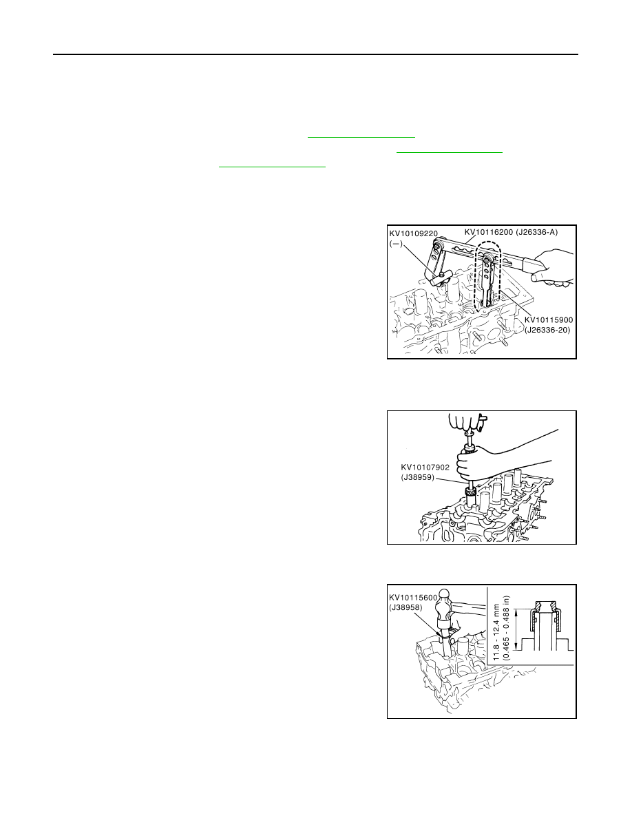
Remove valve collet.
• Compress valve spring with valve spring compressor, attach-
ment and adapter (SST). Remove valve collet with magnetic
hand.
CAUTION:
When working, take care not to damage valve lifter holes.
6.
Remove valve spring retainer and valve spring (with valve spring seat).
CAUTION:
Do not remove valve spring seat from valve spring.
7.
Remove valve oil seal using valve oil seal puller (SST).
INSTALLATION
1.
Apply new engine oil on new valve oil seal joint and seal lip.
2.
Install valve oil seal.
• Install with valve oil seal drift (SST) to match dimension in the
figure.
3.
Install in the reverse order of removal.
Removal and Installation of Front Oil Seal
INFOID:0000000001325794
REMOVAL
PBIC2360E
PBIC0072E
PBIC0073E
OIL SEAL
EM-223
< SERVICE INFORMATION >
[VK45DE]
C
D
E
F
G
H
I
J
K
L
M
A
EM
N
P
O
1.
Remove the following parts:
• Front engine undercover
• Radiator: Refer to
.
• Drive belt: Refer to
• Cooling fan: Refer to
CO-48, "Component (Crankshaft Driven type)"
• Rear plate cover: Refer to
2.
Remove crankshaft pulley as follows:
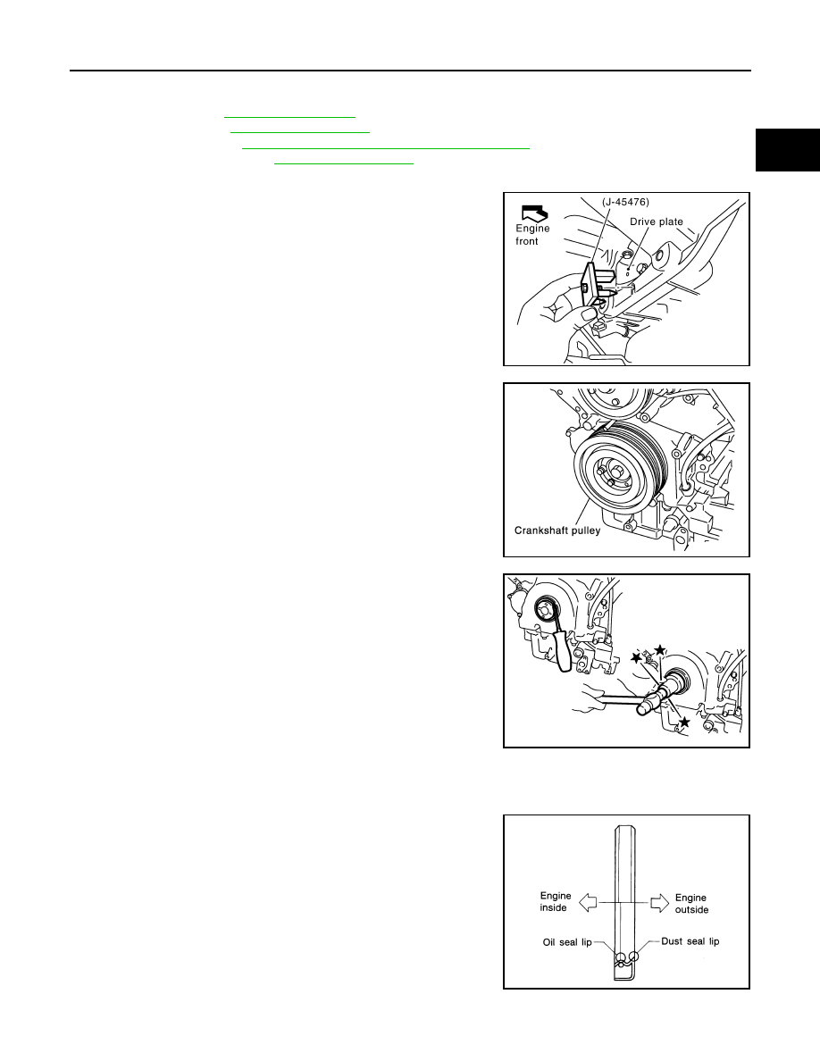
a.
Set ring gear stopper (SST).
b.
Loosen crankshaft pulley bolt, and then pull crankshaft pulley
with both hands to remove it.
CAUTION:
• Do not remove crankshaft pulley bolt. Keep loosened
crankshaft pulley bolt in place to protect removed crank-
shaft pulley from dropping.
• Do not remove balance weight (inner hexagon bolt) at the
front of crankshaft pulley.
3.
Remove front oil seal using suitable tool.
CAUTION:
Be careful not to damage front cover and oil pump drive
spacer.
INSTALLATION
1.
Apply new engine oil to both oil seal lip and dust seal lip of new front oil seal.
2.
Install front oil seal.
• Install front oil seal so that each seal lip is oriented as shown in
the figure.
PBIC1656E
SBIA0358E
SBIA0359E
SEM715A
EM-224
< SERVICE INFORMATION >
[VK45DE]
OIL SEAL
• Using front oil seal drift, press fit until the height of front oil seal
is level with the mounting surface.
• Make sure the garter spring is in position and seal lips not
inverted.
CAUTION:
• Be careful not to damage front cover and oil pump drive
spacer.
• Press fit straight and avoid causing burrs or tilting oil seal.
3.
Install in the reverse order of removal.
Removal and Installation of Rear Oil Seal
INFOID:0000000001325795
REMOVAL
1.
Remove transmission (with transfer) assembly. Refer to
AT-241, "Removal and Installation (2WD Mod-
a.
Remove drive plate. Refer to
.
b.
Remove engine rear plate. Refer to
2.
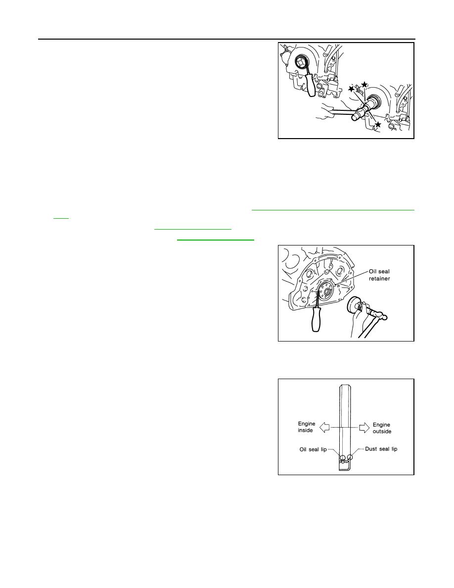
Remove rear oil seal using suitable tool.
CAUTION:
Be careful not to damage crankshaft and oil seal retainer
surface.
INSTALLATION
1.
Apply new engine oil to both oil seal lip and dust seal lip of new rear oil seal.
2.
Install rear oil seal.
• Install rear oil seal so that each seal lip is oriented as shown in
the figure.
Front oil seal drift
Outer diameter
: 56 mm (2.20 in)
Inner diameter
: 49 mm (1.93 in)
SBIA0359E
SBIA0360E
SEM715A
Нет комментариевНе стесняйтесь поделиться с нами вашим ценным мнением.
Текст