Infiniti FX35 / FX45. Manual — part 647
CYLINDER HEAD
EM-105
< SERVICE INFORMATION >
[VQ35DE]
C
D
E
F
G
H
I
J
K
L
M
A
EM
N
P
O
Disassembly and Assembly
INFOID:0000000001325740
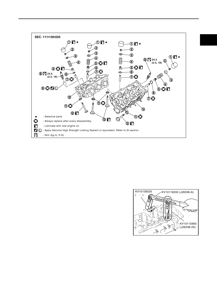
DISASSEMBLY
1.
Remove spark plug with spark plug wrench (commercial service tool).
2.
Remove valve lifter.
• Identify installation positions, and store them without mixing them up.
3.
Remove valve collet.
• Compress valve spring with the valve spring compressor, the
attachment and the adapter (SST). Remove valve collet with a
magnet hand.
CAUTION:
When working, take care not to damage valve lifter holes.
4.
Remove valve spring retainer, valve spring and valve spring seat.
5.
Push valve stem to combustion chamber side, and remove valve.
• Identify installation positions, and store them without mixing them up.
1.
Valve lifter
2.
Valve collet
3.
Valve spring retainer
4.
Valve spring
5.
Valve oil seal
6.
Valve spring seat
7.
Valve guide
8.
Spark plug
9.
Spark plug tube
10. Cylinder head (right bank)
11.
Valve seat
12. Valve (EXH)
13. Valve (INT)
14. Cylinder head (left bank)
PBIC2637E
PBIC1803E
EM-106
< SERVICE INFORMATION >
[VQ35DE]
CYLINDER HEAD
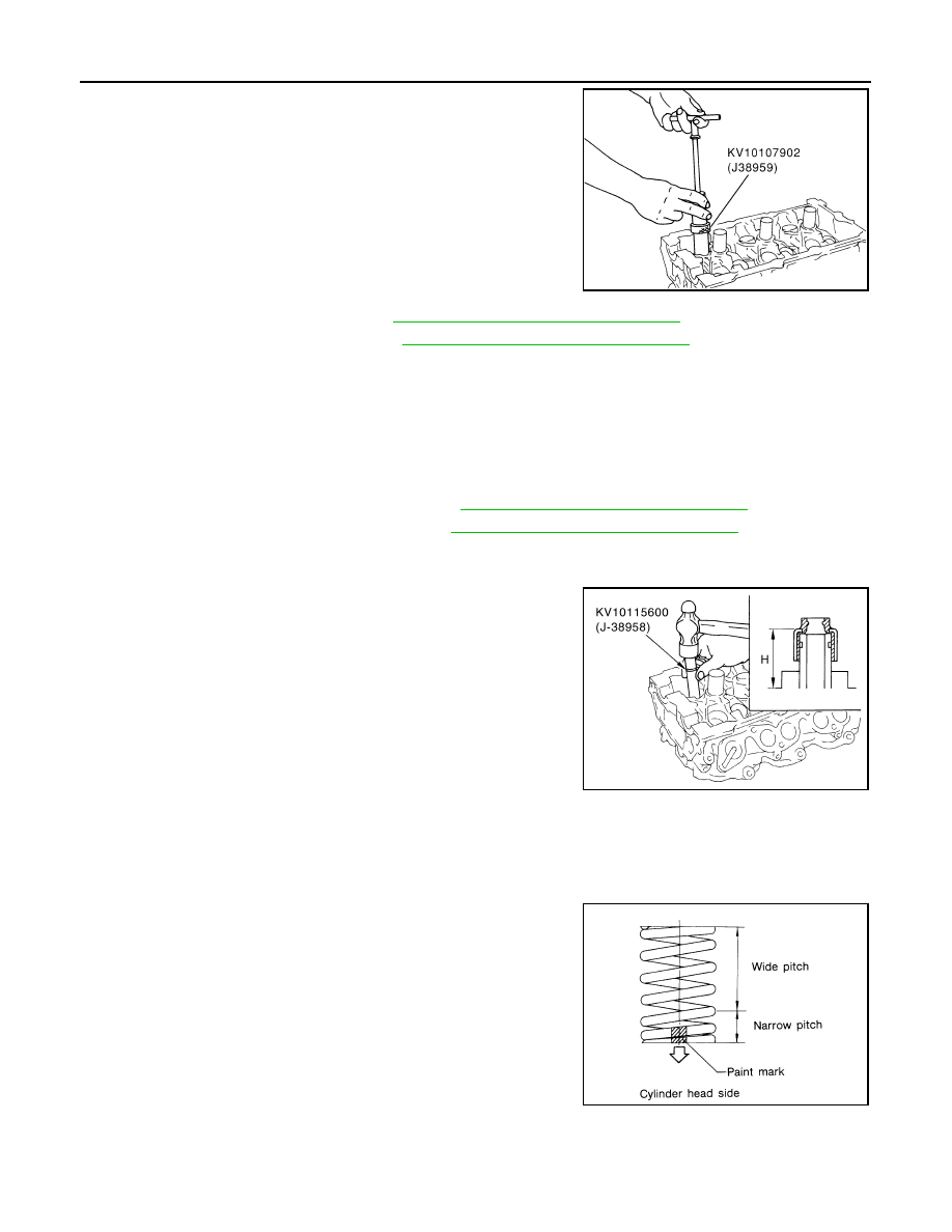
6.
Remove valve oil seal using the valve oil seal puller (SST).
7.
If valve seat must be replaced, refer to
EM-107, "Inspection After Disassembly"
.
8.
If valve guide must be replaced, refer to
EM-107, "Inspection After Disassembly"
.
9.
Remove spark plug tube, as necessary.
• Using a pliers, pull spark plug tube out of cylinder head.
CAUTION:
• Take care not to damage cylinder head.
• Once removed, spark plug tube will be deformed and cannot be reused. Do not remove it unless
absolutely necessary.
ASSEMBLY
1.
When valve guide is removed, install it. Refer to
EM-107, "Inspection After Disassembly"
2.
When valve seat is removed, install it. Refer to
EM-107, "Inspection After Disassembly"
.
3.
Install new valve oil seals as follows:
a.
Apply new engine oil on valve oil seal joint and seal lip.
b.
Install with the valve oil seal drift (SST) to match dimension in
the figure.
4.
Install valve spring seat.
5.
Install valve.
• Larger diameter valves are for intake side.
NOTE:
Larger diameter valves are for intake side.
6.
Install valve spring (uneven pitch type).
• Install narrow pitch end (paint mark) to cylinder head side
(valve spring seat side).
• Intake side and exhaust side valve springs are different. Install
them referring to the following paint mark collar.
7.
Install valve spring retainer.
PBIC0884E
Height “H” (Without valve spring seat installed)
Intake and exhaust
: 14.3 - 14.9 mm (0.563 - 0.587 in)
PBIC2769E
Paint mark collar
Intake and Exhaust
: Blue
SEM085D
CYLINDER HEAD
EM-107
< SERVICE INFORMATION >
[VQ35DE]
C
D
E
F
G
H
I
J
K
L
M
A
EM
N
P
O
8.
Install valve collet.
• Compress valve spring with the valve spring compressor, the
attachment and the adapter (SST). Install valve collet with a
magnet hand.
CAUTION:
When working, take care not to damage valve lifter holes.
• Tap valve stem edge lightly with plastic hammer after installa-
tion to check its installed condition.
9.
Install valve lifter.
• Install it in the original position.
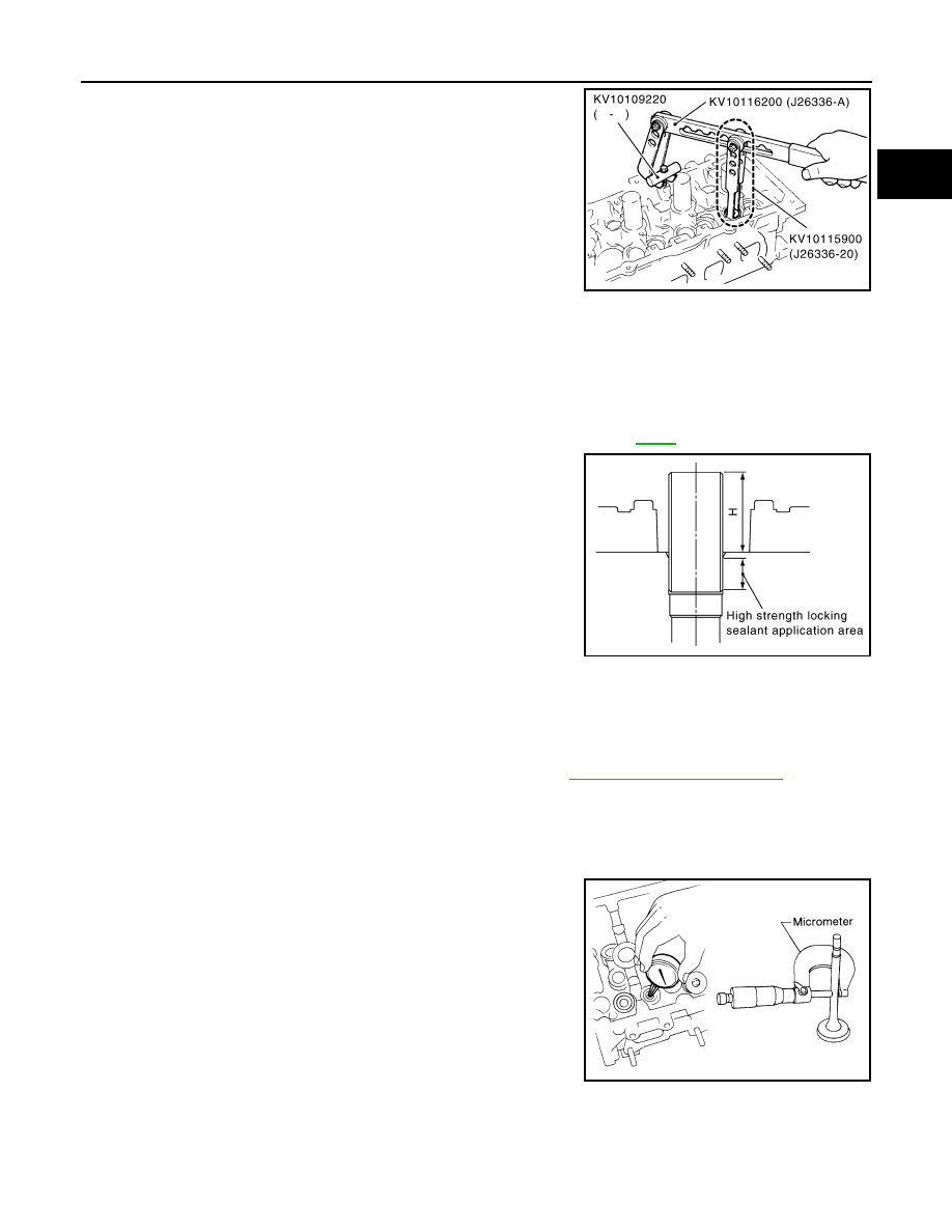
10. Install spark plug tube.
• Press-fit spark plug tube as follows:
a.
Remove old liquid gasket adhering to cylinder head mounting hole.
b.
Apply sealant to area within approximately 12 mm (0.47 in) from edge of spark plug tube press-fit side.
Use Genuine High Strength Locking Sealant or equivalent. Refer to
.
c.
Using drift, press-fit spark plug tube so that its height “H” is as
specified in the figure.
CAUTION:
• When press-fitting, take care not to deform spark plug
tube.
• After press-fitting, wipe off liquid gasket protruding onto
cylinder-head upper face.
11. Install spark plug with spark plug wrench (commercial service tool).
Inspection After Disassembly
INFOID:0000000001325741
VALVE DIMENSIONS
• Check the dimensions of each valve. For the dimensions, refer to
.
• If dimensions are out of the standard, replace valve and check valve seat contact. Refer to "VALVE SEAT
CONTACT".
VALVE GUIDE CLEARANCE
Valve Stem Diameter
Measure the diameter of valve stem with micrometer.
Valve Guide Inner Diameter
Measure the inner diameter of valve guide with an inside micrometer.
PBIC1803E
Standard press-fit height “H”:
: 38.1 - 39.1 mm (1.500 - 1.539 in)
PBIC2638E
Standard
Intake
: 5.965 - 5.980 mm (0.2348 - 0.2354 in)
Exhaust
: 5.955 - 5.970 mm (0.2344 - 0.2350 in)
SEM938C
EM-108
< SERVICE INFORMATION >
[VQ35DE]
CYLINDER HEAD
Valve Guide Clearance
(Valve guide clearance) = (Valve guide inner diameter) – (Valve stem diameter)
• If the calculated value exceeds the limit, replace valve and/or valve guide When valve guide must be
replaced, refer to "VALVE GUIDE REPLACEMENT".
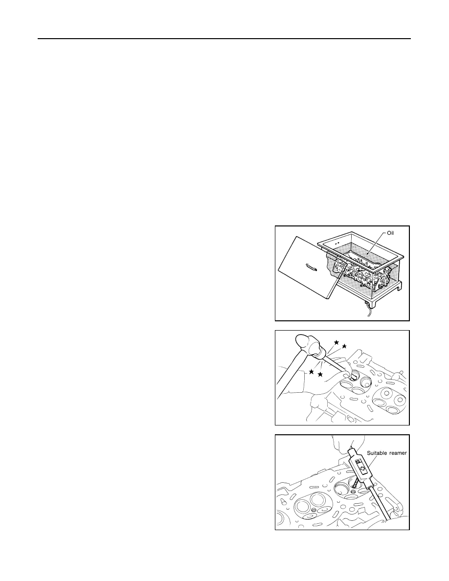
VALVE GUIDE REPLACEMENT
When valve guide is removed, replace with oversized [0.2 mm (0.008 in)] valve guide.
1.
To remove valve guide, heat cylinder head to 110 to 130
°
C (230
to 266
°
F) by soaking in heated oil.
2.
Drive out valve guide with a press [under a 20 kN (2 ton, 2.2 US
ton, 2.0 lmp ton) pressure] or a hammer and the valve guide drift
(commercial service tool).
WARNING:
Cylinder head contains heat. When working, wear protec-
tive equipment to avoid getting burned.
3.
Using the valve guide reamer (commercial service tool), ream
cylinder head valve guide hole.
Standard
Intake and Exhaust
: 6.000 - 6.018 mm (0.2362 - 0.2369 in)
Valve guide clearance:
Standard
Intake
: 0.020 - 0.053 mm (0.0008 - 0.0021 in)
Exhaust
: 0.030 - 0.063 mm (0.0012 - 0.0025 in)
Limit
Intake
: 0.08 mm (0.0031 in)
Exhaust
: 0.10 mm (0.0039 in)
SEM008A
SEM931C
Valve guide hole diameter (for service parts):
Intake and exhaust
: 10.175 - 10.196 mm (0.4006 - 0.4014 in)
SEM932C
Нет комментариевНе стесняйтесь поделиться с нами вашим ценным мнением.
Текст