Infiniti FX35 / FX45. Manual — part 645
OIL SEAL
EM-97
< SERVICE INFORMATION >
[VQ35DE]
C
D
E
F
G
H
I
J
K
L
M
A
EM
N
P
O
OIL SEAL
Removal and Installation of Valve Oil Seal
INFOID:0000000001325734
REMOVAL
1.
Remove camshaft relating to valve oil seal to be removed. Refer to
2.
Remove valve lifters. Refer to
.
3.
Turn crankshaft until the cylinder requiring new oil seals is at TDC. This will prevent valve from dropping
into cylinder.
4.
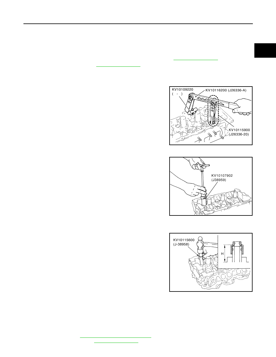
Remove valve collet.
• Compress valve spring with the valve spring compressor, the
attachment, the adapter (SST). Remove valve collet with a
magnet hand.
CAUTION:
When working, take care not to damage valve lifter holes.
5.
Remove valve spring retainer, and valve spring.
6.
Remove valve oil seal using the valve oil seal puller (SST).
INSTALLATION
1.
Apply new engine oil on new valve oil seal joint and seal lip.
2.
Using the valve oil seal drift (SST), press fit valve seal to height
“H” shown in figure.
NOTE:
Dimension “H”: Height measured before valve spring seat instal-
lation
3.
Install in the reverse order of removal after this step.
Removal and Installation of Front Oil Seal
INFOID:0000000001325735
REMOVAL
1.
Remove the following parts:
• Undercover
• Drive belts: Refer to
EM-15, "Removal and Installation"
.
• Crankshaft pulley: Refer to
PBIC1803E
PBIC0884E
Intake and exhaust
: 14.3 - 14.9 mm (0.563 - 0.587 in)
PBIC2769E
EM-98
< SERVICE INFORMATION >
[VQ35DE]
OIL SEAL
2.
Remove front oil seal using a suitable tool.
CAUTION:
Be careful not to damage front timing chain case and crank-
shaft.
INSTALLATION
1.
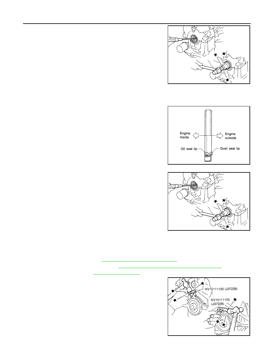
Apply new engine oil to both oil seal lip and dust seal lip of new front oil seal.
2.
Install front oil seal.
• Install front oil seal so that each seal lip is oriented as shown in
the figure.
• Using a suitable drift, press-fit until the height of front oil seal is
level with the mounting surface.
- Suitable drift: outer diameter 60 mm (2.36 in), inner diameter
50 mm (1.97 in).
• Make sure the garter spring is in position and seal lips not
inverted
CAUTION:
• Be careful not to damage front timing chain case and
crankshaft.
• Press-fit straight and avoid causing burrs or tilting oil
seal.
3.
Install in the reverse order of removal after this step.
Removal and Installation of Rear Oil Seal
INFOID:0000000001325736
REMOVAL
1.
Remove oil pan (upper). Refer to
EM-30, "Component (2WD Models)"
2.
Remove transmission assembly. Refer to
AT-241, "Removal and Installation (2WD Models)"
.
3.
Remove drive plate. Refer to
.
4.
Use a seal cutter (SST) to cut away liquid gasket and remove
rear oil seal retainer.
CAUTION:
Be careful not to damage mounting surface.
NOTE:
Regard both rear oil seal and retainer as an assembly.
SEM829E
SEM715A
SEM829E
SEM830E

OIL SEAL
EM-99
< SERVICE INFORMATION >
[VQ35DE]
C
D
E
F
G
H
I
J
K
L
M
A
EM
N
P
O
INSTALLATION
1.
Remove old liquid gasket on mating surfaces of cylinder block and oil pan (upper) using a scraper.
2.
Apply new engine oil to both oil seal lip and dust seal lip of new rear oil seal retainer.
3.
Apply a continuous bead of liquid gasket with the tube presser
(commercial service tool) to rear oil seal retainer as shown in the
figure.
Use Genuine RTV Silicone Sealant or equivalent. Refer to
GI-44, "Recommended Chemical Product and Sealant"
• Assembly should be done within 5 minutes after coating.
4.
Install rear oil seal retainer to cylinder block. Refer to
.
• Make sure the garter spring is in position and seal lips not inverted.
5.
Install in the reverse order of removal after this step.
PBIC2661E
EM-100
< SERVICE INFORMATION >
[VQ35DE]
CYLINDER HEAD
CYLINDER HEAD
On-Vehicle Service
INFOID:0000000001325737
CHECKING COMPRESSION PRESSURE
1.
Warm up engine thoroughly. Then, stop it.
2.
Release fuel pressure. Refer to
3.
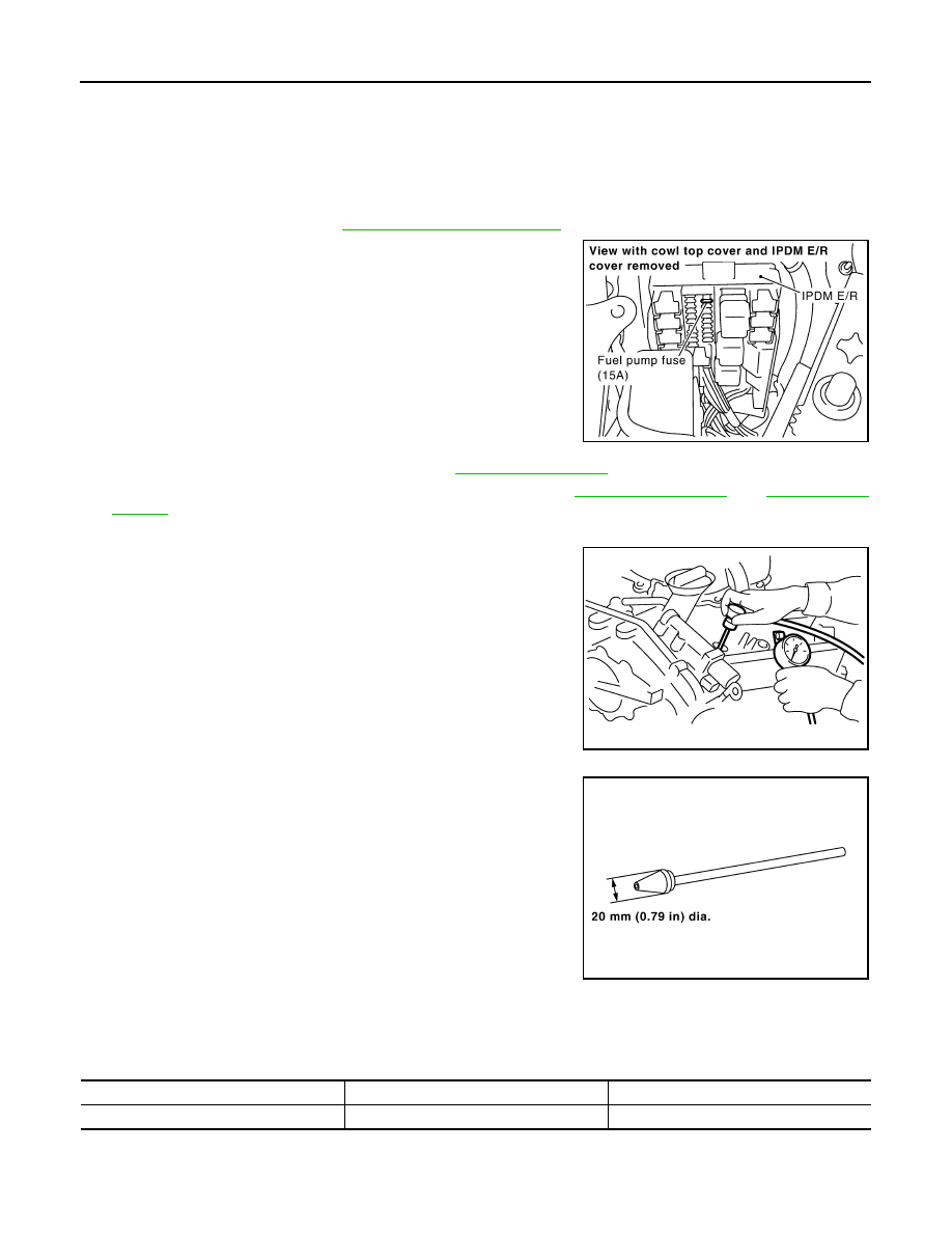
Disconnect fuel pump fuse to avoid fuel injection during mea-
surement.
4.
Remove engine cover with power tool. Refer to
5.
Remove ignition coil and spark plug from each cylinder. Refer to
6.
Connect engine tachometer (not required in use of CONSULT-III).
7.
Install compression gauge with an adapter (commercial service
tool) onto spark plug hole.
• Use the adapter whose picking up end inserted to spark plug
hole is smaller than 20 mm (0.79 in) in diameter. Otherwise, it
may be caught by cylinder head during removal.
8.
Turn ignition switch to “START” for cranking. When the gauge pointer stabilizes, read the compression
pressure and the engine rpm. Perform these steps to check each cylinder.
Compression pressure:
Unit: kPa (kg/cm
2
, psi) /rpm
CAUTION:
Always use a fully changed battery to obtain the specified engine speed.
SBIA0466E
PBIC0900E
SBIA0533E
Standard
Minimum
Deference limit between cylinders
1,275 (13.0, 185)/300
981 (10.0, 142)/300
98 (1.0, 14)/300
Нет комментариевНе стесняйтесь поделиться с нами вашим ценным мнением.
Текст