Infiniti FX35 / FX45. Manual — part 646
CYLINDER HEAD
EM-101
< SERVICE INFORMATION >
[VQ35DE]
C
D
E
F
G
H
I
J
K
L
M
A
EM
N
P
O
• If the engine speed is out of the specified range, check battery liquid for proper gravity. Check the
engine speed again with normal battery gravity.
• If compression pressure is below minimum value, check valve clearances and parts associated with
combustion chamber (valve, valve seat, piston, piston ring, cylinder bore, cylinder head, cylinder head
gasket). After the checking, measure compression pressure again.
• If some cylinder has low compression pressure, pour small amount of engine oil into the spark plug hole
of the cylinder to re-check it for compression.
- If the added engine oil improves the compression, piston rings may be worn out or damaged. Check pis-
ton rings and replace if necessary.
- If the compression pressure remains at low level despite the addition of engine oil, valves may be mal-
functioning. Check valves for damage. Replace valve or valve seat accordingly.
• If two adjacent cylinders have respectively low compression pressure and their compression remains
low even after the addition of engine oil, cylinder head gaskets are leaking. In such a case, replace cyl-
inder head gaskets.
9.
After inspection is completed, install removed parts.
10. Start the engine, and make sure that the engine runs smoothly.
11. Perform trouble diagnosis. If DTC appears, erase it. Refer to
EC-89, "Trouble Diagnosis Introduction"
Component
INFOID:0000000001325738
Removal and Installation
INFOID:0000000001325739
REMOVAL
1.
Remove camshaft. Refer to
.
NOTE:
It is also possible to perform the following steps 2 and 3 just before removing camshaft.
2.
Temporarily fit front suspension member to support engine. Refer to
FSU-16, "Removal and Installation"
.
CAUTION:
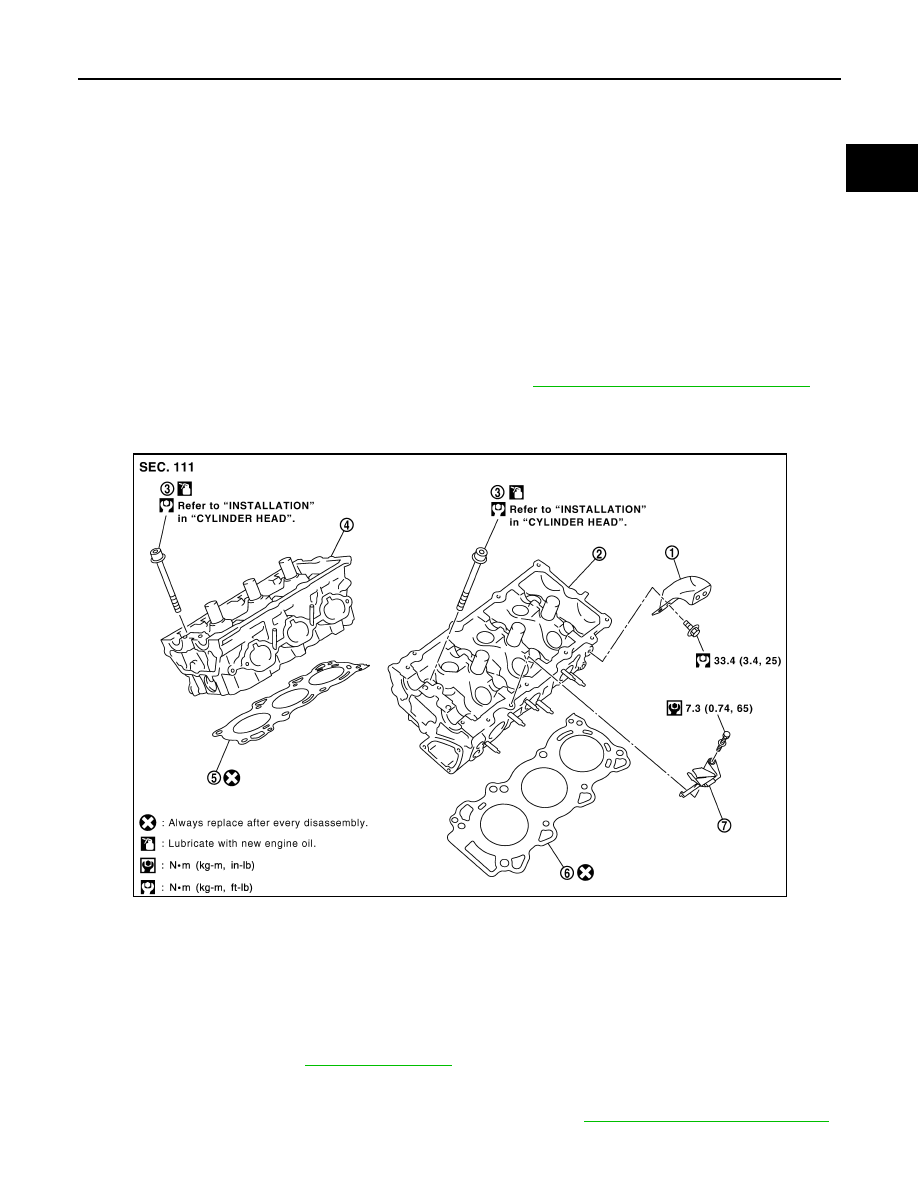
1.
Engine rear lower slinger
2.
Cylinder head (left bank)
3.
Cylinder head bolt
4.
Cylinder head (right bank)
5.
Cylinder head gasket (right bank)
6.
Cylinder head gasket (left bank)
7.
Oil level gauge guide
SBIA0581E

EM-102
< SERVICE INFORMATION >
[VQ35DE]
CYLINDER HEAD
Temporary fitting means the status that engine is adequately stable though the hoist is released
from hanging.
NOTE:
At the time of the start of this procedure front suspension member is removed, and cylinder head is
hanged by hoist with the engine slinger installed.
3.
Release the hoist from hanging, then remove the engine slinger.
4.
Remove the following parts:
• Fuel tube and fuel injector assembly: Refer to
.
• Intake manifold: Refer to
.
• Exhaust manifold: Refer to
.
• Water inlet and thermostat assembly: Refer to
• Water outlet, water pipe and heater pipe: Refer to
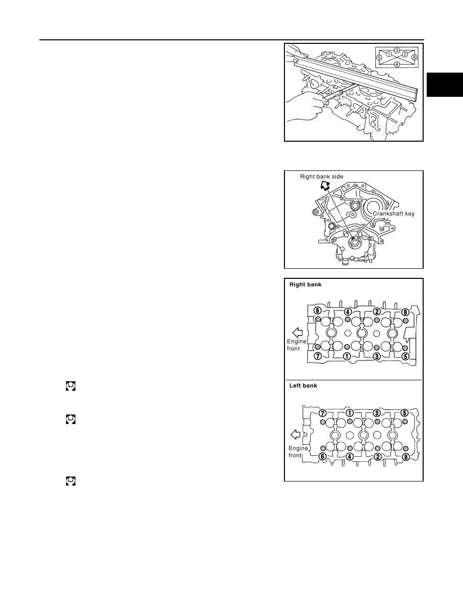
5.
Remove cylinder head bolts in reverse order as shown in the fig-
ure with cylinder head bolt wrench (commercial service tool) and
power tool to remove cylinder heads (right and left banks).
6.
Remove cylinder head gaskets.
INSPECTION AFTER REMOVAL
Cylinder Head Bolts Outer Diameter
• Cylinder head bolts are tightened by plastic zone tightening
method. Whenever the size difference between “d1” and “d2”
exceeds the limit, replace them with new one.
• If reduction of outer diameter appears in a position other than “d2”,
use it as “d2” point.
Cylinder Head Distortion
NOTE:
When performing this inspection, cylinder block distortion should be also checking. Refer to
1.
Using a scraper, wipe off oil, scale, gasket, sealant and carbon deposits from surface of cylinder head.
CAUTION:
Do not allow gasket fragments to enter engine oil or engine coolant passages.
PBIC2057E
Limit (“d1” – “d2”)
: 0.11 mm (0.0043 in)
PBIC2480E
CYLINDER HEAD
EM-103
< SERVICE INFORMATION >
[VQ35DE]
C
D
E
F
G
H
I
J
K
L
M
A
EM
N
P
O
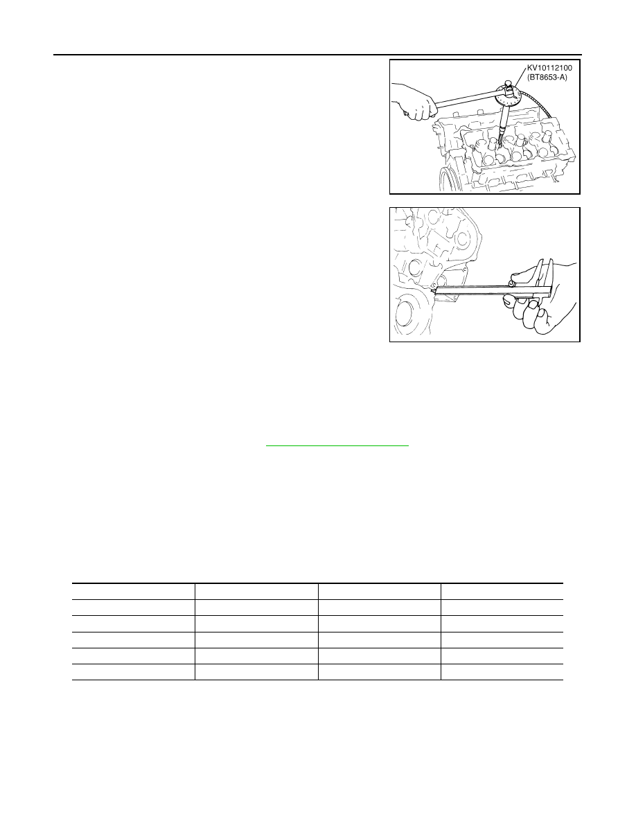
2.
At each of several locations on bottom surface of cylinder head,
measure the distortion in six directions.
• If it exceeds the limit, replace cylinder head.
INSTALLATION
1.
Install new cylinder head gaskets.
2.
Turn crankshaft until No. 1 piston is set at TDC.
• Crankshaft key should line up with the right bank cylinder cen-
ter line as shown in the figure.
3.
Install cylinder head follow the steps below to tighten cylinder
head bolts in numerical order as shown in the figure with cylin-
der head bolts wrench (commercial service tool).
CAUTION:
If cylinder head bolts re-used, check their outer diameters
before installation. Refer to "Cylinder Head Bolts Outer
Diameter".
a.
Apply new engine oil to threads and seat surfaces of cylinder
head bolts.
b.
Tighten all cylinder head bolts.
c.
Completely loosen all cylinder head bolts.
CAUTION:
In step “c”, loosen bolts in reverse order of that indicated in
the figure.
d.
Tighten all cylinder head bolts.
Limit
: 0.1 mm (0.004 in)
SEM861E
SEM532G
: 98.1 N·m (10 kg-m, 72 ft-lb)
: 0 N·m (0 kg-m, 0 ft-lb)
: 39.2 N·m (4.0 kg-m, 29 ft-lb)
PBIC2057E
EM-104
< SERVICE INFORMATION >
[VQ35DE]
CYLINDER HEAD
e.
Turn all cylinder head bolts 90 degrees clockwise (angle tighten-
ing).
CAUTION:
Check the tightening angle by using the angle wrench
(SST). Avoid judgment by visual inspection without SST.
• Check tightening angle indicated on the angle wrench indica-
tor plate.
f.
Turn all cylinder head bolts 90 degrees clockwise again (angle
tightening).
4.
After installing cylinder head, measure distance between front
end faces of cylinder block and cylinder head (left and right
banks).
• If measured value is out of the standard, re-install cylinder
head.
5.
Install in the reverse order of removal after this step.
INSPECTION AFTER INSTALLATION
Inspection for Leaks
The following are procedures for checking fluids leak, lubricates leak and exhaust gases leak.
• Before starting engine, check oil/fluid levels including engine coolant and engine oil. If less than required
quantity, fill to the specified level. Refer to
.
• Use procedure below to check for fuel leakage.
- Turn ignition switch “ON” (with engine stopped). With fuel pressure applied to fuel piping, check for fuel leak-
age at connection points.
- Start engine. With engine speed increased, check again for fuel leakage at connection points.
• Run engine to check for unusual noise and vibration.
• Warm up engine thoroughly to make sure there is no leakage of fuel, exhaust gases, or any oil/fluids includ-
ing engine oil and engine coolant.
• Bleed air from lines and hoses of applicable lines, such as in cooling system.
• After cooling down engine, again check oil/fluid levels including engine oil and engine coolant. Refill to the
specified level, if necessary.
Summary of the inspection items:
*: Transmission/transaxle/CVT fluid. power steering fluid, brake fluid, etc.
PBIC0888E
Standard
: 14.1 - 14.9 mm (0.555 - 0.587 in)
EMQ0662D
Items
Before starting engine
Engine running
After engine stopped
Engine coolant
Level
Leakage
Level
Engine oil
Level
Leakage
Level
Other oils and fluid*
Level
Leakage
Level
Fuel
Leakage
Leakage
Leakage
Exhaust gases
—
Leakage
—
Нет комментариевНе стесняйтесь поделиться с нами вашим ценным мнением.
Текст