Infiniti FX35 / FX45. Manual — part 74
AT-224
< SERVICE INFORMATION >
ON-VEHICLE SERVICE
6.
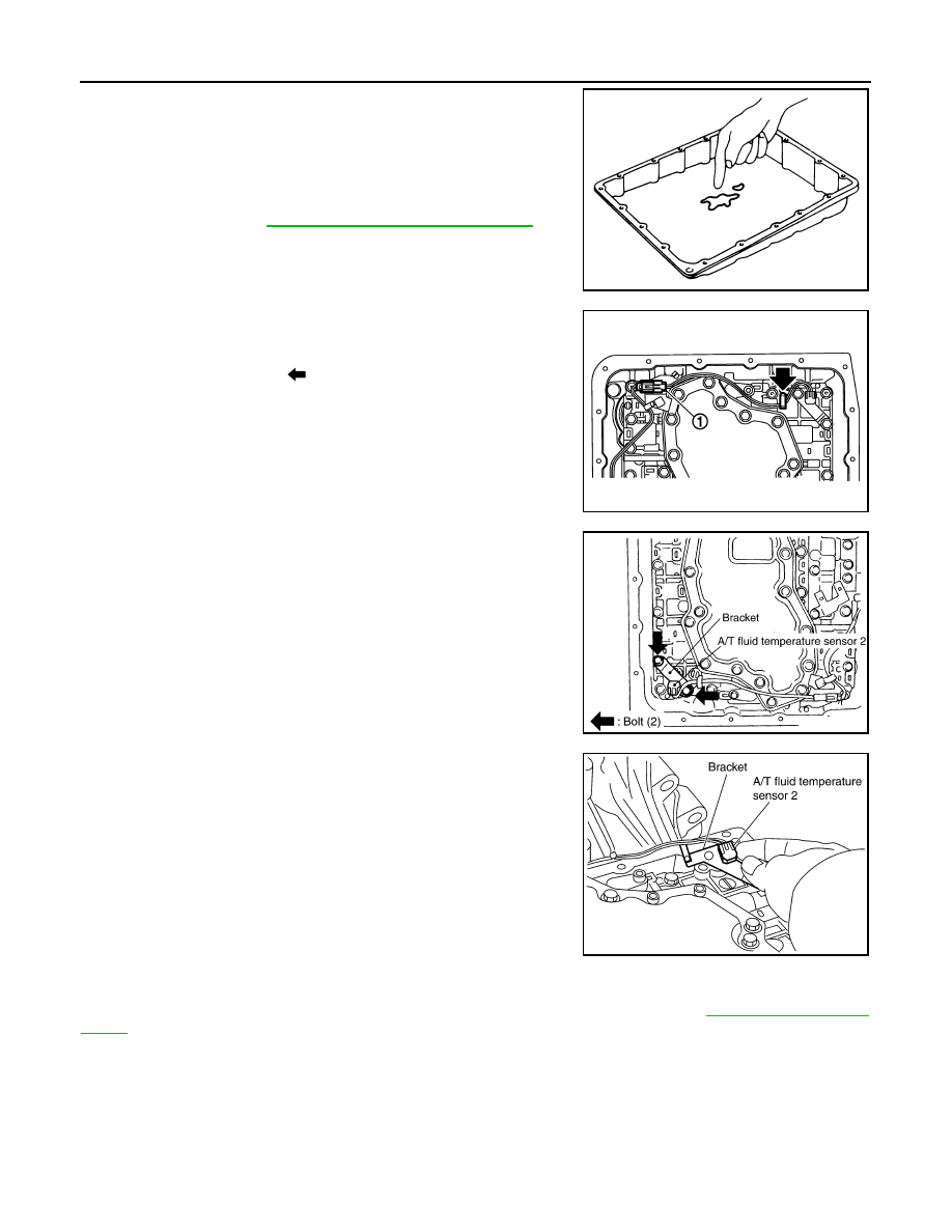
Check foreign materials in oil pan to help determine causes of
malfunction. If the ATF is very dark, smells burned, or contains
foreign particles, the frictional material (clutches, band) may
need replacement. A tacky film that will not wipe clean indicates
varnish build up. Varnish can cause valves, servo, and clutches
to stick and can inhibit pump pressure.
• If frictional material is detected, perform A/T fluid cooler
cleaning. Refer to
AT-13, "A/T Fluid Cooler Cleaning"
7.
Disconnect A/T fluid temperature sensor 2 connector (1).
CAUTION:
Be careful not to damage connector.
8.
Straighten terminal clip (
) to free A/T fluid temperature sensor
2 harness.
9.
Remove A/T fluid temperature sensor 2 with bracket from con-
trol valve with TCM.
10. Remove bracket from A/T fluid temperature sensor 2.
Installation
CAUTION:
After completing installation, check A/T fluid leakage and A/F fluid level. Refer to
.
SCIA5199E
SCIA8076E
SCIA5302E
SCIA5264E
ON-VEHICLE SERVICE
AT-225
< SERVICE INFORMATION >
D
E
F
G
H
I
J
K
L
M
A
B
AT
N
O
P
1.
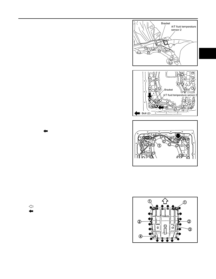
Install A/T fluid temperature sensor 2 to bracket.
2.
Install A/T fluid temperature sensor 2 (with bracket) in control
valve with TCM, and then tighten A/T fluid temperature sensor 2
mounting bolt to the specified torque. Refer to "COMPO-
NENTS".
3.
Connect A/T fluid temperature sensor 2 connector (1).
4.
Securely fasten A/T fluid temperature sensor 2 harness with ter-
minal clip (
).
5.
Install oil pan to transmission case.
a.
Install oil pan gasket to oil pan.
CAUTION:
• Do not reuse oil pan gasket.
• Install it in the direction to align hole positions.
• Completely remove all moisture, oil and old gasket, etc. from oil pan mounting surface.
b.
Install oil pan (3) (with oil pan gasket), clips (2) and brackets (1)
(VK45DE) to transmission case.
•
: Vehicle front
•
: Bolt (22)
CAUTION:
• Install it so that drain plug (4) comes to the position as
shown in the figure.
• Be careful not to pinch harnesses.
• Completely remove all moisture, oil and old gasket, etc.
from oil pan mounting surface.
SCIA5264E
SCIA5302E
SCIA8076E
SCIA8128E
AT-226
< SERVICE INFORMATION >
ON-VEHICLE SERVICE
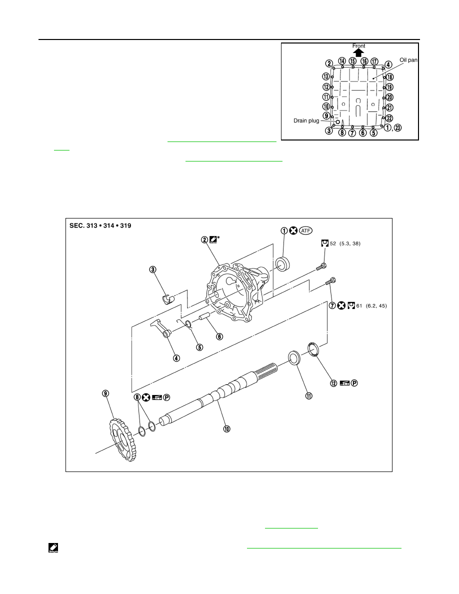
c.
Tighten oil pan mounting bolts to the specified torque in numeri-
cal order shown in the figure after temporarily tightening them.
Refer to "COMPONENTS".
CAUTION:
Do not reuse oil pan mounting bolts.
6.
Install drain plug to oil pan, and then tighten drain plug to the
specified torque. Refer to "COMPONENTS".
CAUTION:
Do not reuse drain plug gasket.
7.
Connect heated oxygen sensor 2 harness connector.
8.
Install front cross bar. Refer to
9.
Pour ATF into A/T assembly. Refer to
10. Connect the battery cable to the negative terminal.
Parking Component (2WD Models Only)
INFOID:0000000001327394
COMPONENTS
REMOVAL
SCIA4113E
1.
Rear oil seal
2.
Rear extension
3.
Parking actuator support
4.
Parking pawl
5.
Return spring
6.
Pawl shaft
7.
Self-sealing bolt
8.
Seal ring
9.
Parking gear
10.
Output shaft
11.
Bearing race
12. Needle bearing
Refer to GI section to make sure icons (symbol marks) in the figure. Refer to
.
However, refer to the following symbol for others.
*
: Apply Genuine Anaerobic Liquid Gasket or equivalent. Refer to
GI-44, "Recommended Chemical Product and Sealant"
SCIA7433E
ON-VEHICLE SERVICE
AT-227
< SERVICE INFORMATION >
D
E
F
G
H
I
J
K
L
M
A
B
AT
N
O
P
1.
Drain ATF through drain plug.
2.
Remove exhaust front tube and center muffler with power tool. Refer to
.
3.
Remove rear propeller shaft. Refer to
PR-9, "Removal and Installation"
4.
Remove control rod. Refer to
AT-206, "Control Rod Removal and Installation"
.
5.
Support A/T assembly with a transmission jack.
CAUTION:
When setting transmission jack, be careful not to allow it to collide against the drain plug.
6.
Remove rear engine mounting member with power tool. Refer to
AT-241, "Removal and Installation (2WD
.
7.
Remove engine mounting insulator (rear). Refer to
AT-241, "Removal and Installation (2WD Models)"
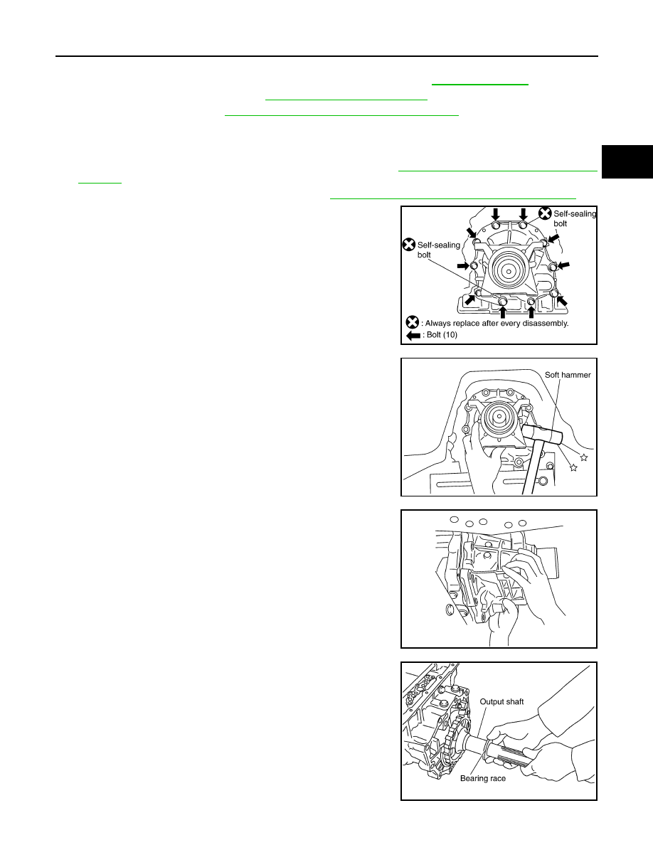
8.
Remove tightening bolts for rear extension assembly and trans-
mission case.
9.
Tap rear extension assembly with soft hammer.
10. Remove rear extension assembly from transmission case. (With
needle bearing.)
11. Remove bearing race from output shaft.
SCIA6941E
SCIA3432E
SCIA3431E
SCIA5245E
Нет комментариевНе стесняйтесь поделиться с нами вашим ценным мнением.
Текст