Infiniti FX35 / FX45. Manual — part 73
AT-220
< SERVICE INFORMATION >
ON-VEHICLE SERVICE
3.
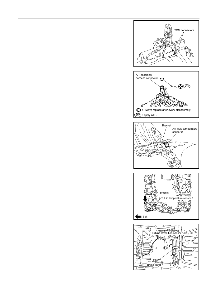
Connect TCM connectors.
4.
Install O-ring in A/T assembly harness connector.
CAUTION:
• Do not reuse O-ring.
• Apply ATF to O-ring.
5.
Install A/T fluid temperature sensor 2 to bracket.
6.
Install A/T fluid temperature sensor 2 (with bracket) in control
valve with TCM, and then tighten A/T fluid temperature sensor 2
mounting bolt to the specified torque. Refer to "COMPO-
NENTS".
CAUTION:
Adjust bolt hole of bracket to bolt hole of control valve with
TCM.
7.
Install control valve with TCM in transmission case.
CAUTION:
• Make sure that turbine revolution sensor securely installs
turbine revolution sensor hole.
• Hang down revolution sensor harness toward outside so
as not to disturb installation of control valve with TCM.
• Adjust A/T assembly harness connector of control valve
with TCM to terminal hole of transmission case.
SCIA5447E
SCIA5155E
SCIA5264E
SCIA5301E
SCIA5034E
ON-VEHICLE SERVICE
AT-221
< SERVICE INFORMATION >
D
E
F
G
H
I
J
K
L
M
A
B
AT
N
O
P
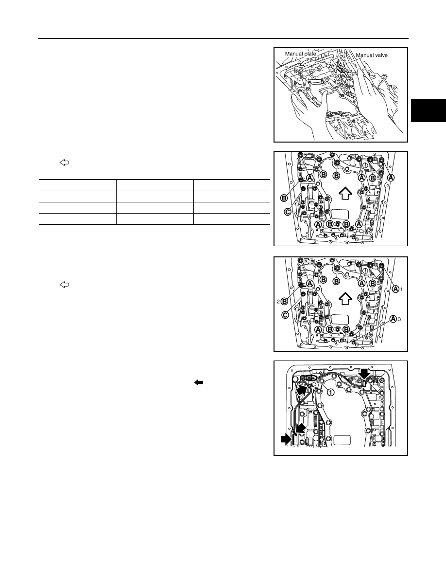
• Assemble it so that manual valve cutout is engaged with
manual plate projection.
8.
Install bolts A, B and C in control valve with TCM.
•
: Vehicle front
9.
Tighten bolt 1, 2 and 3 temporarily to prevent dislocation. After
that tighten them in order (1
→
2
→
3), and then tighten other
bolts to the specified torque. Refer to "COMPONENTS".
•
: Vehicle front
10. Connect A/T fluid temperature sensor 2 connector (1).
11. Securely fasten terminal cord assembly and A/T fluid tempera-
ture sensor 2 harness with terminal clips (
).
SCIA5142E
Bolt symbol
Length mm (in)
Number of bolts
A
42 (1.65)
5
B
55 (2.17)
6
C
40 (1.57)
1
SCIA8074E
SCIA8075E
SCIA8069E
AT-222
< SERVICE INFORMATION >
ON-VEHICLE SERVICE
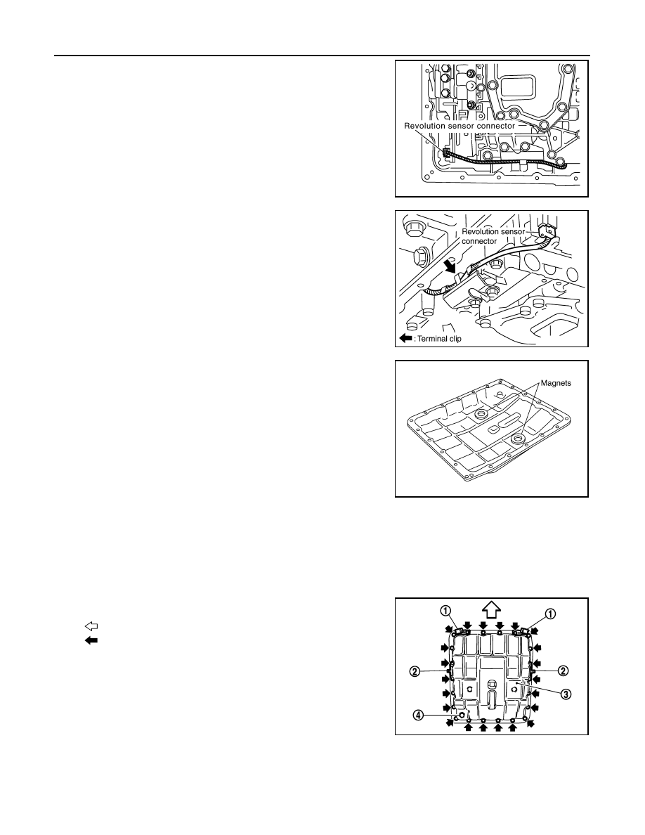
12. Connect revolution sensor connector.
13. Securely fasten revolution sensor harness with terminal clip.
14. Install magnets in oil pan.
15. Install oil pan to transmission case.
a.
Install oil pan gasket to oil pan.
CAUTION:
• Do not reuse oil pan gasket.
• Install it in the direction to align hole positions.
• Completely remove all moisture, oil and old gasket, etc. from oil pan gasket mounting surface.
b.
Install oil pan (3) (with oil pan gasket), clips (2) and brackets (1)
(VK45DE) to transmission case.
•
: Vehicle front
•
: Bolt (22)
CAUTION:
• Install it so that drain plug (4) comes to the position as
shown in the figure.
• Be careful not to pinch harnesses.
• Completely remove all moisture, oil and old gasket, etc.
from oil pan mounting surface.
SCIA7524E
SCIA7525E
SCIA5200E
SCIA8128E

ON-VEHICLE SERVICE
AT-223
< SERVICE INFORMATION >
D
E
F
G
H
I
J
K
L
M
A
B
AT
N
O
P
c.
Tighten oil pan mounting bolts to the specified torque in numeri-
cal order shown in the figure after temporarily tightening them.
Refer to "COMPONENTS".
CAUTION:
Do not reuse oil pan mounting bolts.
16. Install drain plug to oil pan, and then tighten drain plug to the
specified torque. Refer to "COMPONENTS".
CAUTION:
Do not reuse drain plug gasket.
17. Pull up A/T assembly harness connector.
CAUTION:
Be careful not to damage connector.
18. Install snap ring to A/T assembly harness connector.
19. Connect A/T assembly harness connector.
20. Connect heated oxygen sensor 2 harness connector.
21. Install front cross bar. Refer to
22. Pour ATF into A/T assembly. Refer to
.
23. Connect the battery cable to the negative terminal.
A/T FLUID TEMPERATURE SENSOR 2 REMOVAL AND INSTALLATION
Removal
1.
Disconnect the battery cable from the negative terminal.
2.
Remove front cross bar. Refer to
FSU-6, "Removal and Installation"
.
3.
Disconnect heated oxygen sensor 2 harness connector.
4.
Drain ATF through drain plug.
5.
Remove bracket (1) (VK45DE), clips (2), oil pan (3) and oil pan
gasket.
•
: Vehicle front
•
: Bolt (22)
• Drain plug (4)
SCIA4113E
SCIA5038E
SCIA5039E
SCIA8128E
Нет комментариевНе стесняйтесь поделиться с нами вашим ценным мнением.
Текст