Infiniti FX35 / FX45. Manual — part 589
DTC P2135 TP SENSOR
EC-1117
< SERVICE INFORMATION >
[VK45DE]
C
D
E
F
G
H
I
J
K
L
M
A
EC
N
P
O
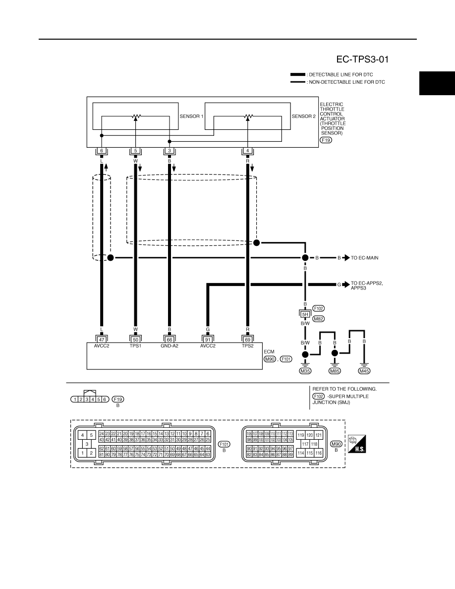
Wiring Diagram
INFOID:0000000001327020
Specification data are reference values and are measured between each terminal and ground.
CAUTION:
Do not use ECM ground terminals when measuring input/output voltage. Doing so may result in dam-
age to the ECM's transistor. Use a ground other than ECM terminals, such as the ground.
TBWM1356E
EC-1118
< SERVICE INFORMATION >
[VK45DE]
DTC P2135 TP SENSOR
Diagnosis Procedure
INFOID:0000000001327021
1.
CHECK GROUND CONNECTIONS
1.
Turn ignition switch OFF.
2.
Loosen and retighten three ground screws on the body.
Refer to
OK or NG
OK
>> GO TO 2.
NG
>> Repair or replace ground connections.
2.
CHECK THROTTLE POSITION SENSOR POWER SUPPLY CIRCUIT-I
TER-
MI-
NAL
NO.
WIRE
COLOR
ITEM
CONDITION
DATA (DC Voltage)
47
L
Sensor power supply (Throt-
tle position sensor)
[Ignition switch: ON]
Approximately 5V
50
W
Throttle position sensor 1
[Ignition switch: ON]
• Engine stopped
• Selector lever: D
• Accelerator pedal: Fully released
More than 0.36V
[Ignition switch: ON]
• Engine stopped
• Selector lever: D
• Accelerator pedal: Fully depressed
Less than 4.75V
66
B
Sensor ground
(Throttle position sensor)
[Engine is running]
• Warm-up condition
• Idle speed
Approximately 0V
69
R
Throttle position sensor 2
[Ignition switch: ON]
• Engine stopped
• Selector lever: D
• Accelerator pedal: Fully released
Less than 4.75V
[Ignition switch: ON]
• Engine stopped
• Selector lever: D
• Accelerator pedal: Fully depressed
More than 0.36V
91
G
Sensor power supply
(APP sensor 2)
[Ignition switch: ON]
Approximately 5V
PBIB2195E
DTC P2135 TP SENSOR
EC-1119
< SERVICE INFORMATION >
[VK45DE]
C
D
E
F
G
H
I
J
K
L
M
A
EC
N
P
O
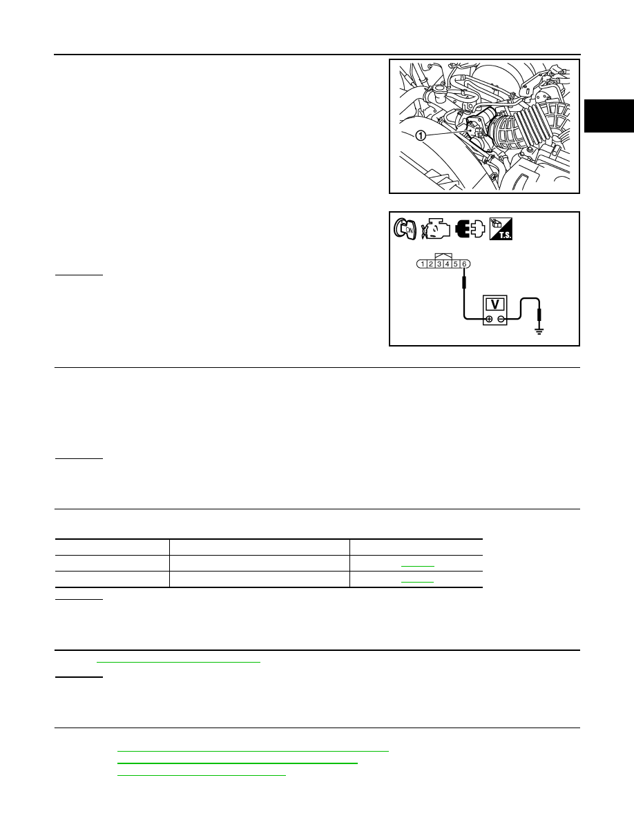
1.
Disconnect electric throttle control actuator (1) harness connec-
tor.
2.
Turn ignition switch ON.
3.
Check voltage between electric throttle control actuator terminal
6 and ground with CONSULT-III or tester.
OK or NG
OK
>> GO TO 7.
NG
>> GO TO 3.
3.
CHECK THROTTLE POSITION SENSOR POWER SUPPLY CIRCUIT-II
1.
Turn ignition switch OFF.
2.
Disconnect ECM harness connector.
3.
Check harness continuity between electric throttle control actuator terminal 6 and ECM terminal 47.
Refer to Wiring Diagram.
OK or NG
OK
>> GO TO 4.
NG
>> Repair open circuit.
4.
CHECK THROTTLE POSITION SENSOR POWER SUPPLY CIRCUIT-III
Check harness for short to power and short to ground, between the following terminals.
OK or NG
OK
>> GO TO 5.
NG
>> Repair short to ground or short to power in harness or connectors.
5.
CHECK APP SENSOR
EC-1115, "Component Inspection"
.
OK or NG
OK
>> GO TO 11.
NG
>> GO TO 6.
6.
REPLACE ACCELERATOR PEDAL ASSEMBLY
1.
Replace accelerator pedal assembly.
2.
EC-662, "Accelerator Pedal Released Position Learning"
.
3.
EC-663, "Throttle Valve Closed Position Learning"
4.
EC-663, "Idle Air Volume Learning"
.
PBIB3232E
Voltage: Approximately 5V
PBIB3250E
Continuity should exist.
ECM terminal
Sensor terminal
Reference Wiring Diagram
47
Electric throttle control actuator terminal 6
91
APP sensor terminal 4

EC-1120
< SERVICE INFORMATION >
[VK45DE]
DTC P2135 TP SENSOR
>> INSPECTION END
7.
CHECK THROTTLE POSITION SENSOR GROUND CIRCUIT FOR OPEN AND SHORT
1.
Turn ignition switch OFF.
2.
Disconnect ECM harness connector.
3.
Check harness continuity between electric throttle control actuator terminal 3 and ECM terminal 66.
Refer to Wiring Diagram.
4.
Also check harness for short to ground and short to power.
OK or NG
OK
>> GO TO 8.
NG
>> Repair open circuit or short to ground or short to power in harness or connectors.
8.
CHECK THROTTLE POSITION SENSOR INPUT SIGNAL CIRCUIT FOR OPEN AND SHORT
1.
Check harness continuity between ECM terminal 50 and electric throttle control actuator terminal 5, ECM
terminal 69 and electric throttle control actuator terminal 4.
Refer to Wiring Diagram.
2.
Also check harness for short to ground and short to power.
OK or NG
OK
>> GO TO 9.
NG
>> Repair open circuit or short to ground or short to power in harness or connectors.
9.
CHECK THROTTLE POSITION SENSOR
EC-1120, "Component Inspection"
.
OK or NG
OK
>> GO TO 11.
NG
>> GO TO 10.
10.
REPLACE ELECTRIC THROTTLE CONTROL ACTUATOR
1.
Replace the electric throttle control actuator.
2.
EC-663, "Throttle Valve Closed Position Learning"
3.
EC-663, "Idle Air Volume Learning"
.
>> INSPECTION END
11.
CHECK INTERMITTENT INCIDENT
>> INSPECTION END
Component Inspection
INFOID:0000000001327022
THROTTLE POSITION SENSOR
1.
Reconnect all harness connectors disconnected.
2.
EC-663, "Throttle Valve Closed Position Learning"
3.
Turn ignition switch ON.
4.
Set selector lever to D position.
Continuity should exist.
Continuity should exist.
Нет комментариевНе стесняйтесь поделиться с нами вашим ценным мнением.
Текст