Infiniti FX35 / FX45. Manual — part 590

DTC P2135 TP SENSOR
EC-1121
< SERVICE INFORMATION >
[VK45DE]
C
D
E
F
G
H
I
J
K
L
M
A
EC
N
P
O
5.
Check voltage between ECM terminals 50 (TP sensor 1 signal),
69 (TP sensor 2 signal) and ground under the following condi-
tions.
6.
If NG, replace electric throttle control actuator and go to the next
step.
7.
EC-663, "Throttle Valve Closed Position Learning"
8.
EC-663, "Idle Air Volume Learning"
.
Removal and Installation
INFOID:0000000001327023
ELECTRIC THROTTLE CONTROL ACTUATOR
.
Terminal
Accelerator pedal
Voltage
50
(Throttle position sensor 1)
Fully released
More than 0.36V
Fully depressed
Less than 4.75V
69
(Throttle position sensor 2)
Fully released
Less than 4.75V
Fully depressed
More than 0.36V
PBIB1530E

EC-1122
< SERVICE INFORMATION >
[VK45DE]
DTC P2138 APP SENSOR
DTC P2138 APP SENSOR
Component Description
INFOID:0000000001327024
The accelerator pedal position sensor is installed on the upper end
of the accelerator pedal assembly. The sensor detects the accelera-
tor position and sends a signal to the ECM.
Accelerator pedal position sensor has two sensors. These sensors
are a kind of potentiometers which transform the accelerator pedal
position into output voltage, and emit the voltage signal to the ECM.
In addition, these sensors detect the opening and closing speed of
the accelerator pedal and feed the voltage signals to the ECM. The
ECM judges the current opening angle of the accelerator pedal from
these signals and controls the throttle control motor based on these
signals.
Idle position of the accelerator pedal is determined by the ECM
receiving the signal from the accelerator pedal position sensor. The ECM uses this signal for the engine oper-
ation such as fuel cut.
CONSULT-III Reference Value in Data Monitor Mode
INFOID:0000000001327025
Specification data are reference values.
*: Accelerator pedal position sensor 2 signal is converted by ECM internally. Thus, it differs from ECM terminal voltage.
On Board Diagnosis Logic
INFOID:0000000001327026
This self-diagnosis has the one trip detection logic.
NOTE:
If DTC P2138 is displayed with DTC P0643, first perform the trouble diagnosis for DTC P0643. Refer to
.
FAIL-SAFE MODE
When the malfunction is detected, ECM enters fail-safe mode and the MIL lights up.
PBIB1741E
MONITOR ITEM
CONDITION
SPECIFICATION
ACCEL SEN 1
• Ignition switch: ON
(Engine stopped)
Accelerator pedal: Fully released
0.5 - 1.0V
Accelerator pedal: Fully depressed
4.0 - 4.8V
ACCEL SEN 2*
• Ignition switch: ON
(Engine stopped)
Accelerator pedal: Fully released
0.3 - 1.2V
Accelerator pedal: Fully depressed
3.9 - 4.8V
CLSD THL POS
• Ignition switch: ON
(Engine stopped)
Accelerator pedal: Fully released
ON
Accelerator pedal: Slightly depressed
OFF
DTC No.
Trouble diagnosis name
DTC detecting condition
Possible cause
P2138
2138
Accelerator pedal posi-
tion sensor circuit range/
performance
Rationally incorrect voltage is sent to ECM
compared with the signals from APP sensor 1
and APP sensor 2.
• Harness or connector
(APP sensor 1 and 2 circuit is open or
shorted.)
(TP sensor circuit is shorted.)
• Accelerator pedal position sensor
(APP sensor 1 and 2)
• Electric throttle control actuator
(TP sensor 1 and 2)
Engine operating condition in fail-safe mode
The ECM controls the electric throttle control actuator in regulating the throttle opening in order for the idle position to be within +10
degrees.
The ECM regulates the opening speed of the throttle valve to be slower than the normal condition.
So, the acceleration will be poor.
DTC P2138 APP SENSOR
EC-1123
< SERVICE INFORMATION >
[VK45DE]
C
D
E
F
G
H
I
J
K
L
M
A
EC
N
P
O
DTC Confirmation Procedure
INFOID:0000000001327027
NOTE:
If DTC Confirmation Procedure has been previously conducted, always turn ignition switch OFF and wait at
least 10 seconds before conducting the next test.
TESTING CONDITION:
Before performing the following procedure, confirm that battery voltage is more than 8V at idle.
1.
Start engine and let it idle for 1 second.
2.
Check DTC.
3.
If DTC is detected, go to
EC-1125, "Diagnosis Procedure"
.
EC-1124
< SERVICE INFORMATION >
[VK45DE]
DTC P2138 APP SENSOR
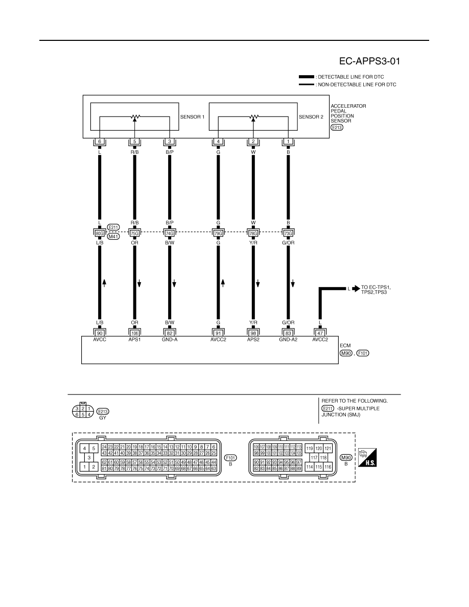
Wiring Diagram
INFOID:0000000001327028
Specification data are reference values and are measured between each terminal and ground.
CAUTION:
Do not use ECM ground terminals when measuring input/output voltage. Doing so may result in dam-
age to the ECM's transistor. Use a ground other than ECM terminals, such as the ground.
TBWM1357E
Нет комментариевНе стесняйтесь поделиться с нами вашим ценным мнением.
Текст