Infiniti FX35 / FX45. Manual — part 666

EXHAUST MANIFOLD AND THREE WAY CATALYST
EM-181
< SERVICE INFORMATION >
[VK45DE]
C
D
E
F
G
H
I
J
K
L
M
A
EM
N
P
O
16. Loosen mounting nuts in reverse order as shown in the figure to
remove exhaust manifold.
NOTE:
Disregard the numerical order No. 9 to 12 in removal.
17. Remove exhaust manifold gaskets.
CAUTION:
Cover engine openings to avoid entry of foreign materials.
INSPECTION AFTER REMOVAL
Surface Distortion
• Check the surface distortion of the each exhaust manifold flange
mating surface with straightedge and feeler gauge.
• If it exceeds the limit, replace exhaust manifold.
INSTALLATION
Note the following, and install in the reverse order of removal.
Exhaust Manifold Gasket
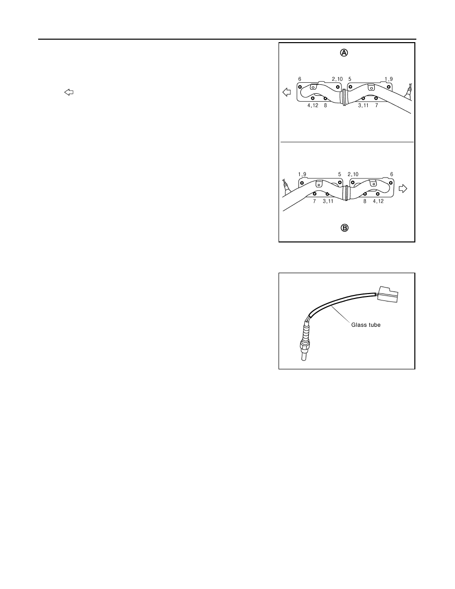
Install exhaust manifold gasket with its directional protrusion set upward.
Refer to the figure of components on former page. Refer to "Removal and Installation".
Exhaust Manifold
A
: Left bank
B
: Right bank
: Engine front
PBIC3300E
Limit
: 0.3 mm (0.012 in)
PBIC1550E
EM-182
< SERVICE INFORMATION >
[VK45DE]
EXHAUST MANIFOLD AND THREE WAY CATALYST
• Install exhaust manifold and tighten mounting nuts in numerical
order as shown in the figure.
NOTE:
Tighten mounting nuts No. 1 to 4 in two steps. The numerical order
No. 9 to 12 shown second steps.
Air Fuel Ratio Sensor and Heated Oxygen Sensor
• Install air fuel ratio sensors and heated oxygen sensors in the original position.
• Install referring the following if the installation positions cannot be
identified.
CAUTION:
• Before installing a new air fuel ratio sensor and heated oxy-
gen sensor, clean exhaust system threads using oxygen sen-
sor thread cleaner (commercial service tool: J-43897-18 or J-
43897-12), and apply anti-seize lubricant (commercial service
tool).
• Do not over torque air fuel ratio sensor and heated oxygen sensor. Doing so may cause damage to
the heated oxygen sensor, resulting in “MIL” coming on.
A
: Left bank
B
: Right bank
: Engine front
PBIC3300E
Glass tube color
Air fuel ratio sensor 1
: Black
Heated oxygen sensor 2
: White
PBIC2652E

OIL PAN AND OIL STRAINER
EM-183
< SERVICE INFORMATION >
[VK45DE]
C
D
E
F
G
H
I
J
K
L
M
A
EM
N
P
O
OIL PAN AND OIL STRAINER
Component
INFOID:0000000001325778
• Refer to
Removal and Installation
INFOID:0000000001325779
REMOVAL
WARNING:
To avoid the danger of being scalded, do not drain engine oil when engine is hot.
1.
Remove front road wheels and tires.
2.
Remove hood assembly. Refer to
3.
Remove engine cover with power tool. Refer to
4.
Remove front and rear engine undercovers with power tool.
5.
Drain engine oil. Refer to
CAUTION:
• Perform this step when engine is cold.
1.
Oil pan
2.
O-ring
3.
Crankshaft position sensor (POS)
4.
Baffle plate
5.
O-ring
6.
Baffle plate
7.
Oil pressure switch
8.
Gasket
9.
Oil strainer
10.
Drain plug
11.
Drain plug washer
12.
O-ring
13.
Oil cooler
14. Connector bolt
15.
Oil filter
16.
O-ring
17. Axle pipe
18.
O-ring
19.
Rear plate cover
20. Relief valve
A.
Oil pan side
B.
Refer to
C.
PBIC4556E
EM-184
< SERVICE INFORMATION >
[VK45DE]
OIL PAN AND OIL STRAINER
• Do not spill engine oil on drive belts.
6.
Drain engine coolant. Refer to
CO-37, "Changing Engine Coolant"
.
CAUTION:
• Perform this step when engine is cold.
• Do not spill engine coolant on drive belts.
7.
Remove drive belts. Refer to
.
8.
Remove auto tensioner of power steering oil pump belt. Refer to
EM-172, "Drive Belt Auto Tensioner and
.
9.
Remove power steering oil pump with piping connected, and temporarily secure it aside with ropes or
equivalent. Refer to
PS-27, "On-Vehicle Inspection and Service"
.
10. Remove A/C compressor with piping connected, and temporarily secure it aside with ropes or equivalent.
11. Remove A/C compressor fitting bolts, and install A/C compressor temporarily on vehicle side with ropes or
equivalent.
12. Remove harness of lower side of oil pan.
13. Remove crankshaft position sensor (POS) from transmission.
CAUTION:
• Handle carefully to avoid dropping and shocks.
• Do not disassemble it.
• Do not allow metal powder to adhere to magnetic part at sensor tip.
• Do not place sensors in a location where they are exposed to magnetism.
14. Install engine slinger and hang engine assembly to secure position. Refer to
.
15. Remove front suspension member with power tool. Refer to
FSU-16, "Removal and Installation"
16. Remove front final drive assembly. Refer to
FFD-14, "Removal and Installation (VQ35DE Models)"
17. Remove oil filter. Refer to
LU-26, "Removal and Installation"
18. Disconnect oil cooler water hoses, and remove oil cooler water pipe and oil cooler. Refer to
19. Remove oil pan as the follows:
a.
Remove rear plate cover.
b.
Remove transmission joint bolts which pierce oil pan. Refer to
AT-243, "Removal and Installation (AWD
.
c.
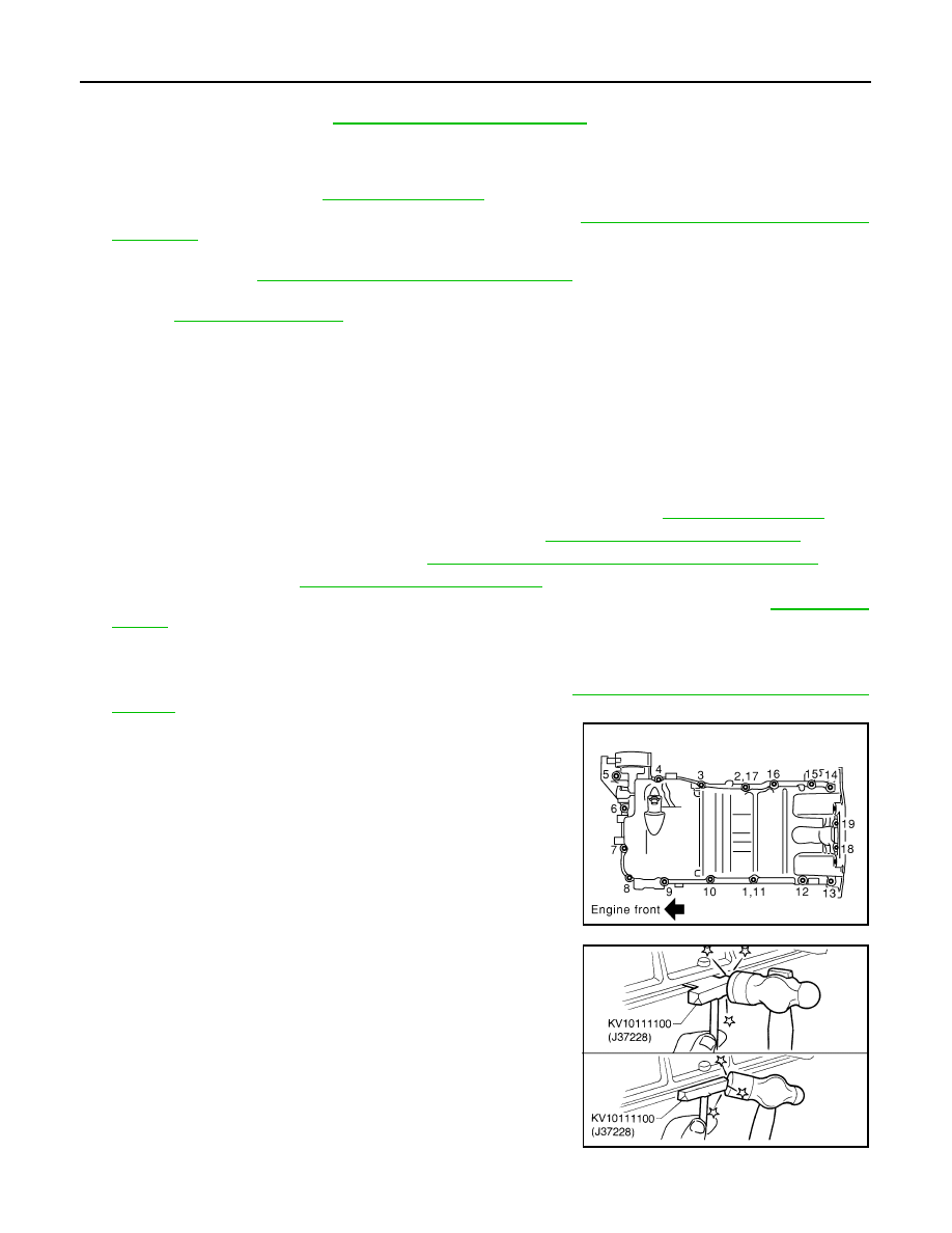
Loosen mounting bolts with power tool in reverse order as
shown in the figure.
NOTE:
Disregard the numerical order No. 11 and 17 in removal.
d.
Insert seal cutter (SST) between oil pan and cylinder block.
Slide seal cutter by tapping on the side of seal cutter with ham-
mer. Remove oil pan.
CAUTION:
• Be careful not to damage the mating surfaces.
• Do not insert screwdriver, this will damage the mating
surface.
e.
Remove O-rings from bottom of oil pump and front cover.
20. As necessary, pull axle pipe from oil pan.
PBIC0194E
SEM365E
Нет комментариевНе стесняйтесь поделиться с нами вашим ценным мнением.
Текст