Infiniti FX35 / FX45. Manual — part 677
OIL SEAL
EM-225
< SERVICE INFORMATION >
[VK45DE]
C
D
E
F
G
H
I
J
K
L
M
A
EM
N
P
O
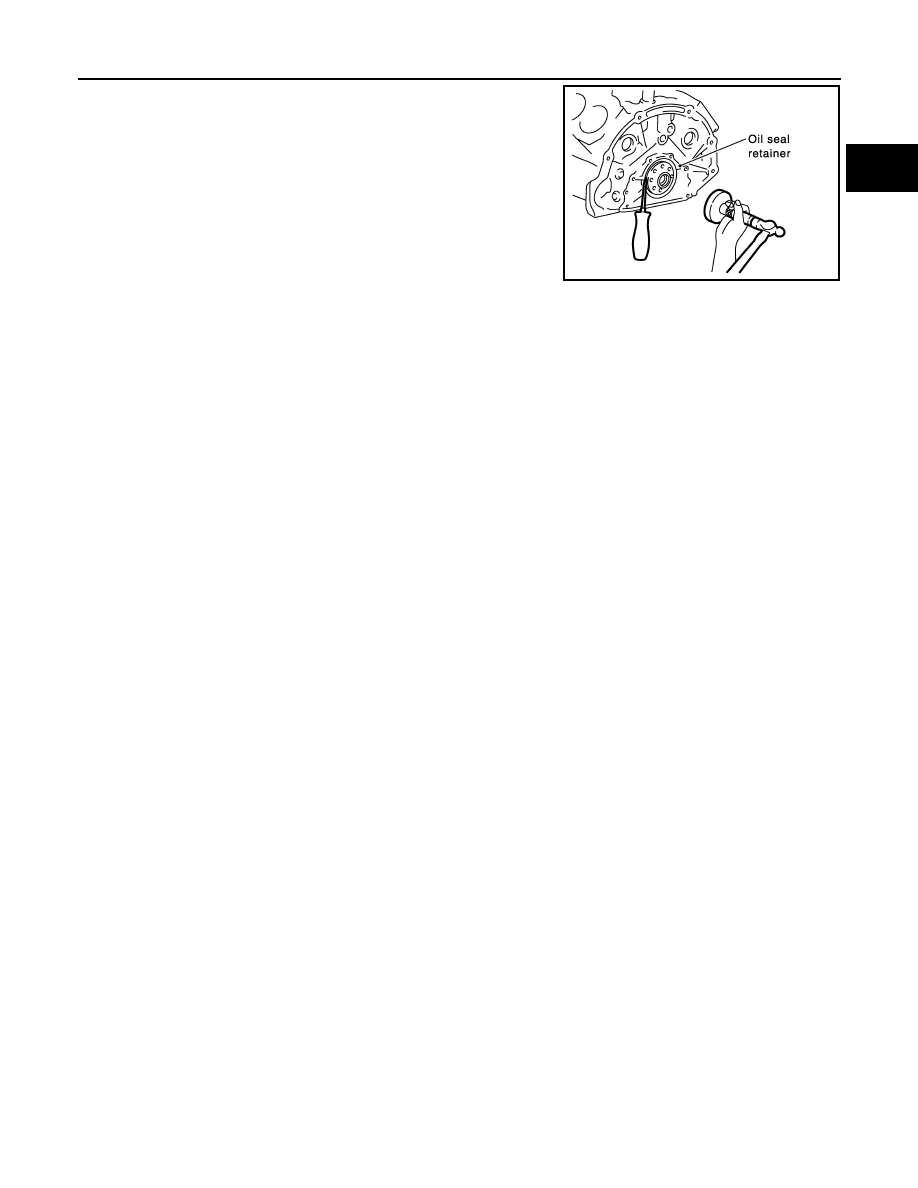
• Using rear oil seal drift (commercial service tool), press fit until
the height of front oil seal is level with the mounting surface.
• Make sure the garter spring is in position and seal lips not
inverted.
CAUTION:
• Be careful not to damage crankshaft and rear oil seal
retainer.
• Press fit straight and avoid causing burrs or tilting oil seal.
3.
Install in the reverse order of removal.
Rear oil seal drift
Outer diameter
: 102 mm (4.02 in)
Inner diameter
: 86 mm (3.39 in)
SBIA0360E
EM-226
< SERVICE INFORMATION >
[VK45DE]
CYLINDER HEAD
CYLINDER HEAD
On-Vehicle Service
INFOID:0000000001325796
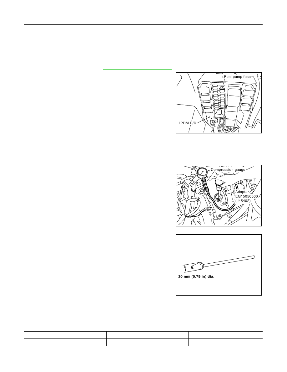
CHECKING COMPRESSION PRESSURE
1.
Warm up engine thoroughly. Then, stop it.
2.
Release fuel pressure. Refer to
.
a.
Remove fuel pump fuse to avoid fuel injection during measure-
ment.
3.
Remove engine cover with power tool. Refer to
4.
Remove ignition coil and spark plug from each cylinder. Refer to
and
.
5.
Connect engine tachometer (not required in use of CONSULT-III).
6.
Install compression gauge with adapter (SST or commercial ser-
vice tool) onto spark plug hole.
• Use compression gauge adapter (SST) which is required on
No. 7 and 8 cylinders.
• Use compression gauge adapter (if no SST is used) whose
picking up end inserted to spark plug hole is smaller than 20
mm (0.79 in) in diameter. Otherwise, it may be caught by cylin-
der head during removal.
7.
With accelerator pedal fully depressed, turn ignition switch to “START” for cranking. When the gauge
pointer stabilizes, read the compression pressure and engine rpm. Perform these steps to check each cyl-
inder.
Compression pressure:
Unit: kPa (kg/cm
2
, psi)/rpm
CAUTION:
Always use a fully changed battery to obtain the specified engine speed.
PBIB1482E
PBIC1554E
SBIA0533E
Standard
Minimum
Deferential limit between cylinders
1,320 (13.5, 191)/300
1,130 (11.5, 164)/300
98 (1.0, 14)/300
CYLINDER HEAD
EM-227
< SERVICE INFORMATION >
[VK45DE]
C
D
E
F
G
H
I
J
K
L
M
A
EM
N
P
O
• If the engine speed is out of specified range, check battery liquid for proper gravity. Check engine speed
again with normal battery gravity.
• If compression pressure is below minimum value, check valve clearances and parts associated with
combustion chamber (valve, valve seat, piston, piston ring, cylinder bore, cylinder head, cylinder head
gasket). After the checking, measure compression pressure again.
• If some cylinders have low compression pressure, pour small amount of engine oil into the spark plug
hole of the cylinder to re-check it for compression.
- If the added engine oil improves the compression, piston rings may be worn out or damaged. Check the
piston rings and replace if necessary.
- If the compression pressure remains at low level despite the addition of engine oil, valves may be mal-
functioning. Check valves for damage. Replace valve or valve seat accordingly.
• If two adjacent cylinders have respectively low compression pressure and their compression remains
low even after the addition of engine oil, cylinder head gaskets are leaking. In such a case, replace cyl-
inder head gaskets.
8.
After inspection is completed, install removed parts in the reverse order of removal.
9.
Start engine, and make sure that engine runs smoothly.
10. Perform trouble diagnosis. If DTC appears, erase it. Refer to
EC-666, "Trouble Diagnosis Introduction"
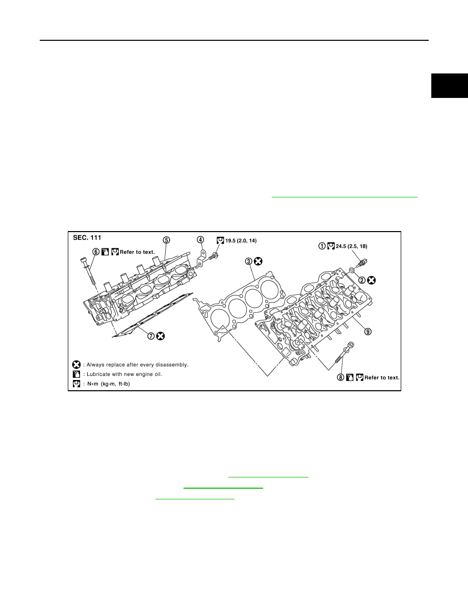
Component
INFOID:0000000001325797
Removal and Installation
INFOID:0000000001325798
REMOVAL
1.
Remove engine assembly from vehicle. Refer to
2.
Remove exhaust manifold. Refer to
.
3.
Remove camshaft. Refer to
1.
Engine coolant temperature sensor
2.
Washer
3.
Cylinder head gasket (left bank)
4.
Harness bracket
5.
Cylinder head (right bank)
6.
Cylinder head bolt
7.
Cylinder head gasket (right bank)
8.
Cylinder head bolt
9.
Cylinder head (left bank)
PBIC2756E
EM-228
< SERVICE INFORMATION >
[VK45DE]
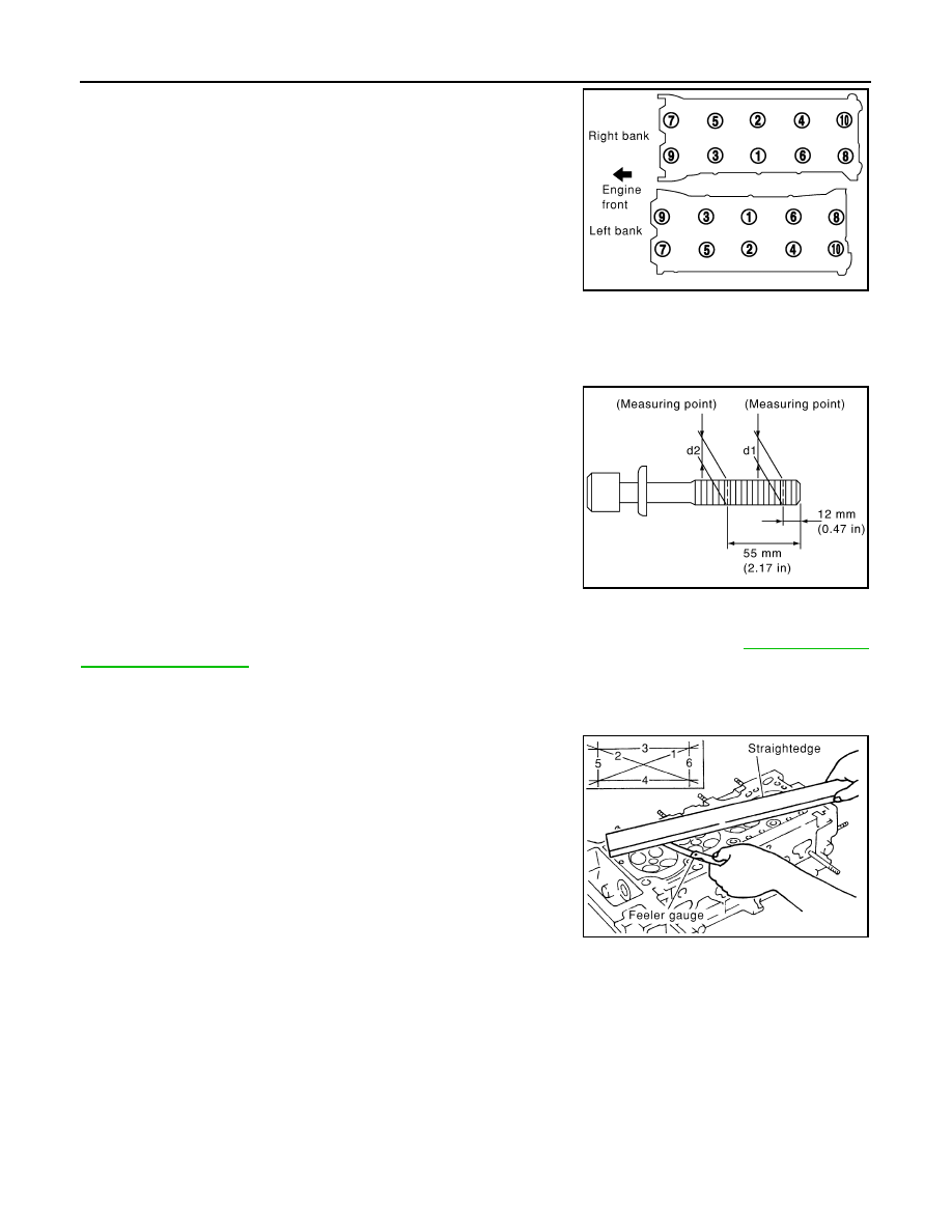
CYLINDER HEAD
4.
Remove cylinder head bolts in reverse order as shown in the fig-
ure with cylinder head bolt wrench (commercial service tool) to
remove cylinder heads (right and left banks).
5.
Remove cylinder head gaskets.
INSPECTION AFTER REMOVAL
Cylinder Head Bolts Outer Diameter
• Cylinder head bolts are tightened by plastic zone tightening
method. Whenever the size difference between “d1” and “d2”
exceeds the limit, replace them with new one.
• If reduction of outer diameter appears in a position other than “d2”,
use it as “d2” point.
Cylinder Head Distortion
NOTE:
When performing this inspection, cylinder block distortion should be also checking. Refer to
1.
Using scraper, wipe off oil, scale, gasket, sealant and carbon deposits from surface of cylinder head.
CAUTION:
Do not allow gasket fragments to enter engine oil or engine coolant passages.
2.
At each of several locations on bottom surface of cylinder head,
measure the distortion in six directions.
• If it exceeds the limit, replace cylinder head.
INSTALLATION
1.
Install new cylinder head gasket.
2.
Turn crankshaft until No. 1 piston is set at TDC.
PBIC0068E
Limit (“d1” – “d2”)
: 0.18 mm (0.0071 in)
PBIC2361E
Limit
: 0.1 mm (0.004 in)
PBIC0075E
Нет комментариевНе стесняйтесь поделиться с нами вашим ценным мнением.
Текст