Infiniti FX35 / FX45. Manual — part 591
DTC P2138 APP SENSOR
EC-1125
< SERVICE INFORMATION >
[VK45DE]
C
D
E
F
G
H
I
J
K
L
M
A
EC
N
P
O
Diagnosis Procedure
INFOID:0000000001327029
1.
CHECK GROUND CONNECTIONS
1.
Turn ignition switch OFF.
2.
Loosen and retighten three ground screws on the body.
Refer to
OK or NG
OK
>> GO TO 2.
NG
>> Repair or replace ground connections.
2.
CHECK APP SENSOR 1 POWER SUPPLY CIRCUIT
TER-
MI-
NAL
NO.
WIRE
COLOR
ITEM
CONDITION
DATA (DC Voltage)
47
L
Sensor power supply (Throt-
tle position sensor)
[Ignition switch: ON]
Approximately 5V
82
B/W
Sensor ground
(APP sensor 1 / ICC steering
switch / ASCD steering
switch)
[Engine is running]
• Warm-up condition
• Idle speed
Approximately 0V
83
G/OR
Sensor ground
(APP sensor 2)
[Engine is running]
• Warm-up condition
• Idle speed
Approximately 0V
90
L/B
Sensor power supply
(APP sensor 1)
[Ignition switch: ON]
Approximately 5V
91
G
Sensor power supply
(APP sensor 2)
[Ignition switch: ON]
Approximately 5V
98
Y/R
Accelerator pedal position
sensor 2
[Ignition switch: ON]
• Engine stopped
• Accelerator pedal: Fully released
0.15 - 0.60V
[Ignition switch: ON]
• Engine stopped
• Accelerator pedal: Fully depressed
1.95 - 2.40V
106
OR
Accelerator pedal position
sensor 1
[Ignition switch: ON]
• Engine stopped
• Accelerator pedal: Fully released
0.5 - 1.0V
[Ignition switch: ON]
• Engine stopped
• Accelerator pedal: Fully depressed
3.9 - 4.7V
PBIB2195E
EC-1126
< SERVICE INFORMATION >
[VK45DE]
DTC P2138 APP SENSOR
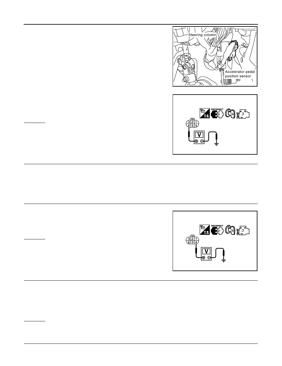
1.
Disconnect accelerator pedal position (APP) sensor harness
connector.
2.
Turn ignition switch ON.
3.
Check voltage between APP sensor terminal 6 and ground with
CONSULT-III or tester.
OK or NG
OK
>> GO TO 4.
NG
>> GO TO 3.
3.
DETECT MALFUNCTIONING PART
Check the following.
• Harness connectors E211, M41
• Harness for open or short between ECM and accelerator pedal position sensor
>> Repair open circuit or short to ground or short to power in harness or connectors.
4.
CHECK APP SENSOR 2 POWER SUPPLY CIRCUIT-I
1.
Turn ignition switch ON.
2.
Check voltage between APP sensor terminal 4 and ground with
CONSULT-III or tester.
OK or NG
OK
>> GO TO 10.
NG
>> GO TO 5.
5.
CHECK APP SENSOR 2 POWER SUPPLY CIRCUIT-II
1.
Turn ignition switch OFF.
2.
Disconnect ECM harness connector.
3.
Check harness continuity between APP sensor terminal 4 and ECM terminal 91.
Refer to Wiring Diagram.
OK or NG
OK
>> GO TO 7.
NG
>> GO TO 6.
6.
DETECT MALFUNCTIONING PART
Check the following.
PBIB1548E
Voltage: Approximately 5V
PBIB0914E
Voltage: Approximately 5V
PBIB0915E
Continuity should exist.

DTC P2138 APP SENSOR
EC-1127
< SERVICE INFORMATION >
[VK45DE]
C
D
E
F
G
H
I
J
K
L
M
A
EC
N
P
O
• Harness connectors E211, M41
• Harness for open or short between ECM and accelerator pedal position sensor
>> Repair open circuit.
7.
CHECK APP SENSOR 2 POWER SUPPLY CIRCUIT-III
Check harness for short to power and short to ground, between the following terminals.
OK or NG
OK
>> GO TO 8.
NG
>> Repair short to ground or short to power in harness or connectors.
8.
CHECK THROTTLE POSITION SENSOR
EC-1120, "Component Inspection"
.
OK or NG
OK
>> GO TO 16.
NG
>> GO TO 9.
9.
REPLACE ELECTRIC THROTTLE CONTROL ACTUATOR
1.
Replace the electric throttle control actuator.
2.
EC-663, "Throttle Valve Closed Position Learning"
3.
EC-663, "Idle Air Volume Learning"
.
>> INSPECTION END
10.
CHECK APP SENSOR GROUND CIRCUIT FOR OPEN AND SHORT
1.
Turn ignition switch OFF.
2.
Disconnect ECM harness connector.
3.
Check harness continuity between APP sensor terminal 3 and ECM terminal 82, APP sensor terminal 1
and ECM terminal 83.
Refer to Wiring Diagram.
4.
Also check harness for short to ground and short to power.
OK or NG
OK
>> GO TO 12.
NG
>> GO TO 11.
11.
DETECT MALFUNCTIONING PART
Check the following.
• Harness connectors E211, M41
• Harness for open or short between ECM and accelerator pedal position sensor
>> Repair open circuit or short to ground or short to power in harness or connectors.
12.
CHECK APP SENSOR INPUT SIGNAL CIRCUIT FOR OPEN AND SHORT
1.
Check harness continuity between ECM terminal 106 and APP sensor terminal 5, ECM terminal 98 and
APP sensor terminal 2.
Refer to Wiring Diagram.
2.
Also check harness for short to ground and short to power.
ECM terminal
Sensor terminal
Reference Wiring Diagram
91
APP sensor terminal 4
47
Electric throttle control actuator terminal 6
Continuity should exist.
Continuity should exist.
EC-1128
< SERVICE INFORMATION >
[VK45DE]
DTC P2138 APP SENSOR
OK or NG
OK
>> GO TO 14.
NG
>> GO TO 13.
13.
DETECT MALFUNCTIONING PART
Check the following.
• Harness connectors E211, M41
• Harness for open or short between ECM and accelerator pedal position sensor
>> Repair open circuit or short to ground or short to power in harness or connectors.
14.
CHECK APP SENSOR
EC-1128, "Component Inspection"
.
OK or NG
OK
>> GO TO 16.
NG
>> GO TO 15.
15.
REPLACE ACCELERATOR PEDAL ASSEMBLY
1.
Replace accelerator pedal assembly.
2.
EC-662, "Accelerator Pedal Released Position Learning"
3.
EC-663, "Throttle Valve Closed Position Learning"
4.
EC-663, "Idle Air Volume Learning"
.
>> INSPECTION END
16.
CHECK INTERMITTENT INCIDENT
>> INSPECTION END
Component Inspection
INFOID:0000000001327030
ACCELERATOR PEDAL POSITION SENSOR
1.
Reconnect all harness connectors disconnected.
2.
Turn ignition switch ON.
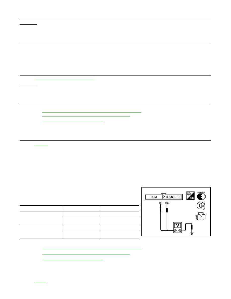
3.
Check voltage between ECM terminals 106 (APP sensor 1 sig-
nal), 98 (APP sensor 2 signal) and ground under the following
conditions.
4.
If NG, replace accelerator pedal assembly and go to next step.
5.
EC-662, "Accelerator Pedal Released Position Learning"
6.
EC-663, "Throttle Valve Closed Position Learning"
7.
EC-663, "Idle Air Volume Learning"
.
Removal and Installation
INFOID:0000000001327031
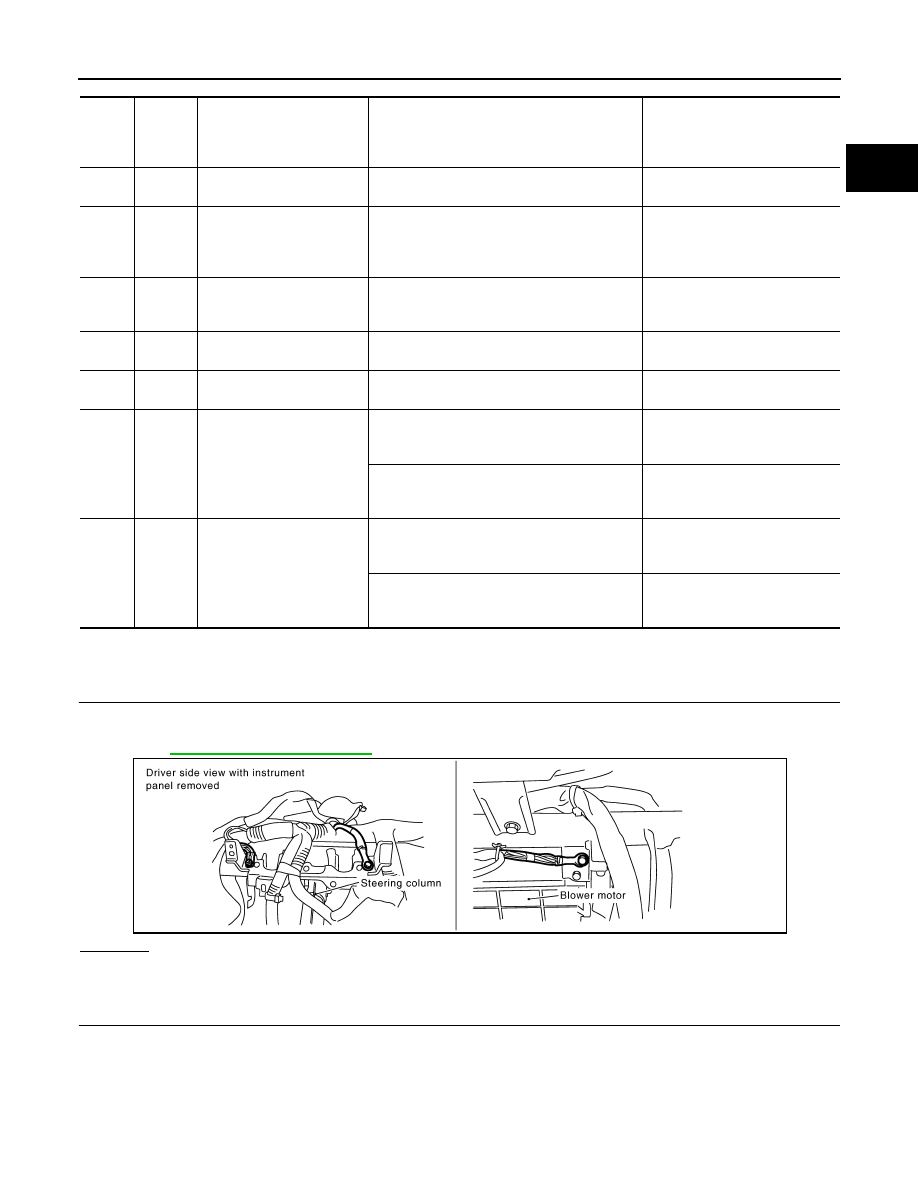
ACCELERATOR PEDAL
Terminal
Accelerator pedal
Voltage
106
(Accelerator pedal position
sensor 1)
Fully released
0.5 - 1.0V
Fully depressed
3.9 - 4.7V
98
(Accelerator pedal position
sensor 2)
Fully released
0.15 - 0.60V
Fully depressed
1.95 - 2.40V
MBIB0023E
Нет комментариевНе стесняйтесь поделиться с нами вашим ценным мнением.
Текст