Infiniti FX35 / FX45. Manual — part 926
SE-62
< SERVICE INFORMATION >
AUTOMATIC DRIVE POSITIONER
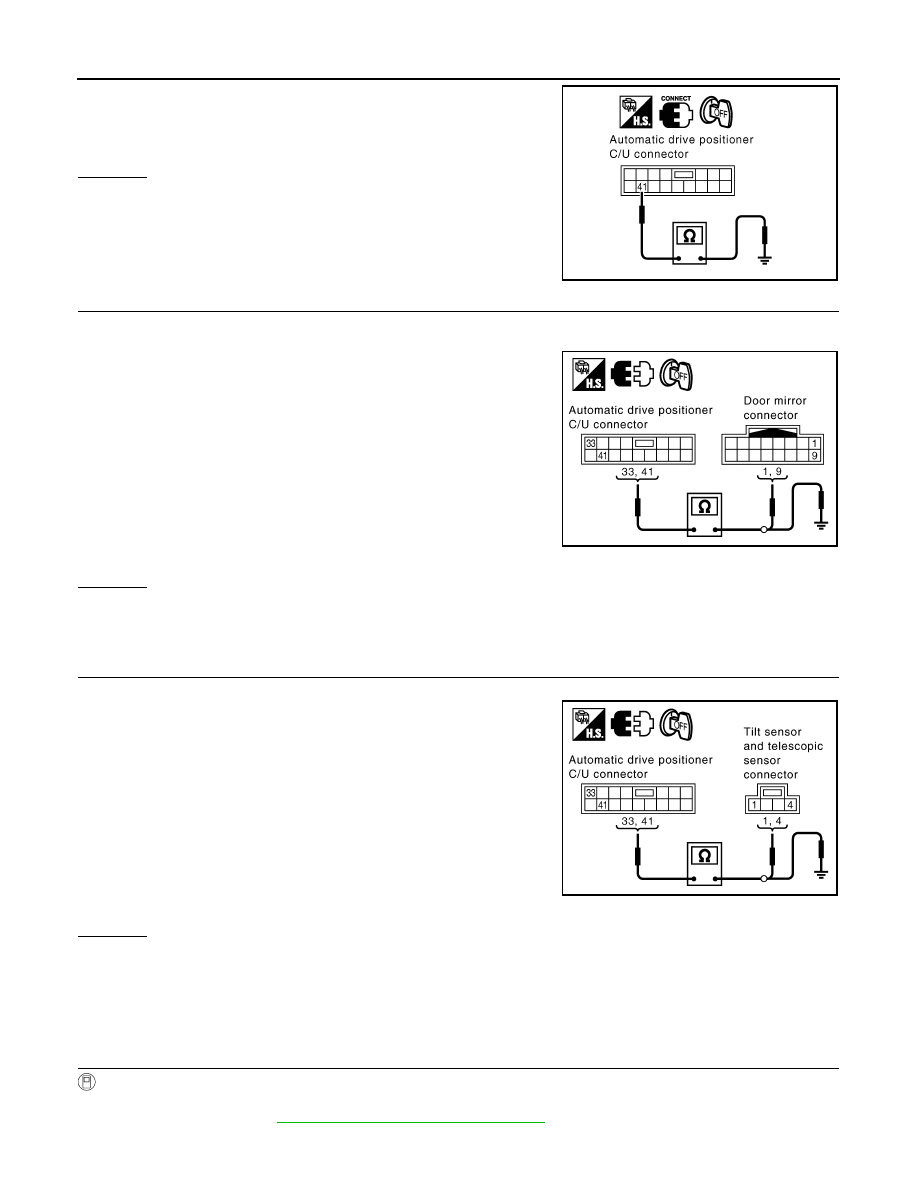
Check continuity between automatic drive positioner control unit
connector M50 terminal 41 and ground.
OK or NG
OK
>> • GO TO 3. (Door mirror sensor)
• GO TO 4. (Steering sensor)
NG
>> Replace automatic drive positioner control unit.
3.
CHECK HARNESS CONTINUITY (DOOR MIRROR SENSOR)
1.
Disconnect automatic drive positioner control unit and door mirror (driver side or passenger side) connec-
tor.
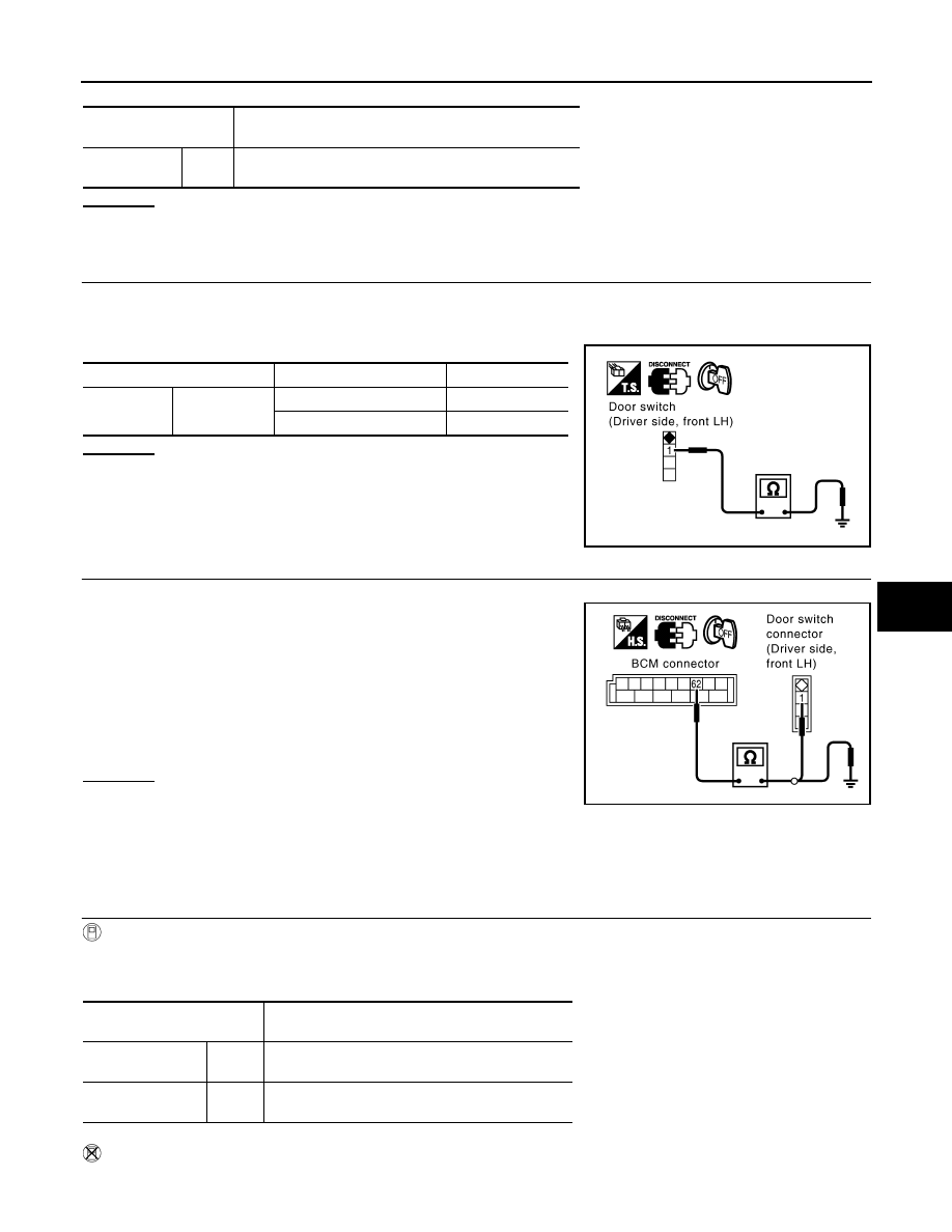
2.
Check continuity between automatic drive positioner control unit
connector M50 terminal 33, 41 and door mirror connector D2
(driver side) or D32 (passenger side) terminal 1, 9.
3.
Check continuity between automatic drive positioner control unit
connector M50 terminal 33, 41 and ground.
OK or NG
OK
>> Check the condition of the harness and connector.
NG
>> Repair or replace harness between automatic drive positioner control unit and door mirror (driver
side or passenger side).
4.
CHECK HARNESS CONTINUITY (STEERING SENSOR)
1.
Disconnect automatic drive positioner control unit and tilt sensor and telescopic sensor connector.
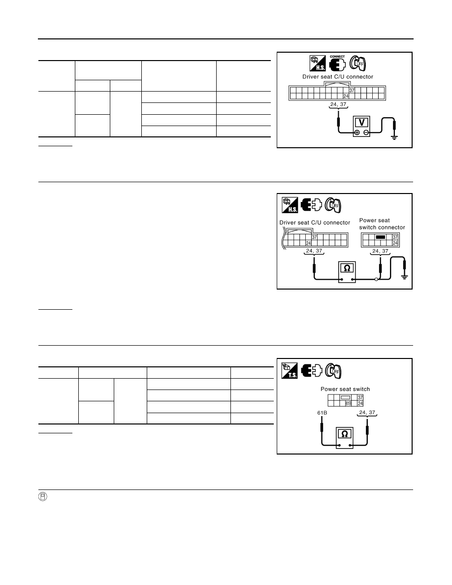
2.
Check continuity between automatic drive positioner control unit
connector M50 terminal 33, 41 and tilt sensor and telescopic
sensor connector M28 terminal 1, 4.
3.
Check continuity between automatic drive positioner control unit
connector M50 terminal 33, 41 and ground.
OK or NG
OK
>> Check the condition of the harness and connector.
NG
>> Repair or replace harness between automatic drive positioner control unit and tilt sensor and tele-
scopic sensor.
Check Front Door Switch (Driver Side) Circuit
INFOID:0000000001328128
1.
CHECK FUNCTION (WITH CONSULT-III)
With CONSULT-III
Touch “BCM” with “DOOR SW-DR” on the DATA MONITOR, check ON/OFF operation when the driver door is
open and closed. *: Refer to
BL-36, "CONSULT-III Function (BCM)"
41 (B/Y) – Ground
: Continuity should exist.
PIIA4779E
33 (G/W) – 1 (OR)
: Continuity should exist.
41 (B/Y) – 9 (BR)
: Continuity should exist.
33 (G/W) – Ground
: Continuity should not exist.
41 (B/Y) – Ground
: Continuity should not exist.
PIIB8586E
33 (G/W) – 1 (G/W)
: Continuity should exist.
41 (B/Y) – 4 (B/Y)
: Continuity should exist.
33 (G/W) – Ground
: Continuity should not exist.
41 (B/Y) – Ground
: Continuity should not exist.
PIIB8588E
AUTOMATIC DRIVE POSITIONER
SE-63
< SERVICE INFORMATION >
C
D
E
F
G
H
J
K
L
M
A
B
SE
N
O
P
OK or NG
OK
>> Front door switch (driver side) circuit is OK.
NG
>> GO TO 2.
2.
CHECK FRONT DOOR SWITCH (DRIVER SIDE)
1.
Turn ignition switch OFF.
2.
Disconnect front door switch connector.
3.
Check continuity between front door switch connector and ground part of door switch.
OK or NG
OK
>> GO TO 3.
NG
>> Replace front door switch (driver side).
3.
CHECK FRONT DOOR (DRIVER SIDE) HARNESS CONTINUITY
1.
Disconnect BCM connector.
2.
Check continuity between BCM connector B14 terminal 62 and
front door switch connector B26 terminal 1.
3.
Check continuity between BCM connector B14 terminal 62 and
ground.
OK or NG
OK
>> Front door switch (driver side) circuit is OK.
NG
>> Repair or replace harness between BCM and front door
switch (driver side).
Check Sliding Switch Circuit
INFOID:0000000001328129
1.
CHECK FUNCTION
With CONSULT-III
With “SLIDE SW-FR, SLIDE SW-RR” on the DATA MONITOR, operate the sliding switch to check ON/OFF
operation.
Without CONSULT-III
1.
Turn ignition switch OFF.
Monitor item
[OPERATION or UNIT]
Contents
DOOR SW*
DR
“ON/
OFF”
Door open (ON)/door closed (OFF) status judged from the
driver door switch is displayed.
Terminals
Door switch
Continuity
1
Ground part of
door switch
Pushed
No
Released
Yes
PIIA5091E
62 (W) – 1 (W)
: Continuity should exist.
62 (W) – Ground
: Continuity should not exist.
PIIA5090E
Monitor item
[OPERATION or UNIT]
Contents
SLIDE SW – FR
“ON/
OFF”
ON/OFF status judged from the sliding switch
(FR) signal is displayed.
SLIDE SW – RR
“ON/
OFF”
ON/OFF status judged from the sliding switch
(RR) signal is displayed.
SE-64
< SERVICE INFORMATION >
AUTOMATIC DRIVE POSITIONER
2.
Sliding switch operate, check voltage between driver seat control unit connector and ground.
OK or NG
OK
>> Sliding switch circuit is OK.
NG
>> GO TO 2.
2.
CHECK HARNESS CONTINUITY
1.
Disconnect driver seat control unit connector and power seat switch connector.
2.
Check continuity between driver seat control unit connector
B152 terminals 24, 37 and power seat switch connector B175
terminals 24, 37.
3.
Check continuity between driver seat control unit connector
B152 terminals 24, 37 and ground.
OK or NG
OK
>> GO TO 3.
NG
>> Repair or replace harness between driver seat control unit and power seat switch.
3.
CHECK SLIDING SWITCH
Sliding switch operate, check continuity between power seat switch connector B175 terminal 24, 27 and 61B.
OK or NG
OK
>> Check the condition of the harness and connector.
NG
>> Replace power seat switch.
Check Reclining Switch Circuit
INFOID:0000000001328130
1.
CHECK FUNCTION
With CONSULT-III
With “RECLINING SW-FR, RECLINING SW-RR” on the DATA MONITOR, operate the reclining switch to
check ON/OFF operation.
Connector
Terminals
(Wire color)
Sliding switch condition
Voltage (V) (Ap-
prox.)
(+)
(-)
B152
24 (L/R)
Ground
FORWARD
0
Other than above
Battery voltage
37 (W)
BACKWARD
0
Other than above
Battery voltage
PIIA6711E
24 (L/R) – 24 (L/R)
: Continuity should exist.
37 (W) – 37 (W)
: Continuity should exist.
24 (L/R) – Ground
: Continuity should not exist.
37 (W) – Ground
: Continuity should not exist.
PIIB8589E
Connector
Terminal
Sliding switch condition
Continuity
B175
24
61B
FORWARD
Yes
Other than above
No
37
BACKWARD
Yes
Other than above
No
PIIB8590E

AUTOMATIC DRIVE POSITIONER
SE-65
< SERVICE INFORMATION >
C
D
E
F
G
H
J
K
L
M
A
B
SE
N
O
P
Without CONSULT-III
1.
Turn ignition switch OFF.
2.
Reclining switch operate, check voltage between driver seat control unit connector and ground.
OK or NG
OK
>> Reclining switch circuit is OK.
NG
>> GO TO 2.
2.
CHECK HARNESS CONTINUITY
1.
Disconnect driver seat control unit connector and power seat switch connector.
2.
Check continuity between driver seat control unit connector
B152 terminals 25, 38 and power seat switch connector B175
terminals 25, 38.
3.
Check continuity between driver seat control unit connector
B152 terminals 25, 38 and ground.
OK or NG
OK
>> GO TO 3.
NG
>> Repair or replace harness between driver seat control unit and power seat switch.
3.
CHECK RECLINING SWITCH
Reclining switch operate, check continuity between power seat switch connector B175 terminal 25, 38 and
61B.
OK or NG
OK
>> Check the condition of the harness and connector.
NG
>> Replace power seat switch.
Monitor item
[OPERATION or UNIT]
Contents
RECLN SW – FR
“ON/
OFF”
ON/OFF status judged from the reclining switch
(FR) signal is displayed.
RECLN SW – RR
“ON/
OFF”
ON/OFF status judged from the reclining switch
(RR) signal is displayed.
Connector
Terminals
(Wire color)
Reclining switch
condition
Voltage (V) (Ap-
prox.)
(+)
(–)
B152
25 (L/OR)
Ground
FORWARD
0
Other than above
Battery voltage
38 (LG/B)
BACKWARD
0
Other than above
Battery voltage
PIIA6095E
25 (L/OR) – 25 (L/OR)
: Continuity should exist.
38 (LG/B) – 38 (LG/B)
: Continuity should exist.
25 (LO/R) – Ground
: Continuity should not exist.
38 (LG/B) – Ground
: Continuity should not exist.
PIIB8591E
Connector
Terminal
Reclining switch condition
Continuity
B175
25
61B
FORWARD
Yes
Other than above
No
38
BACKWARD
Yes
Other than above
No
PIIB8592E
Нет комментариевНе стесняйтесь поделиться с нами вашим ценным мнением.
Текст