Infiniti FX35 / FX45. Manual — part 136
ATC-140
< SERVICE INFORMATION >
REFRIGERANT LINES
2.
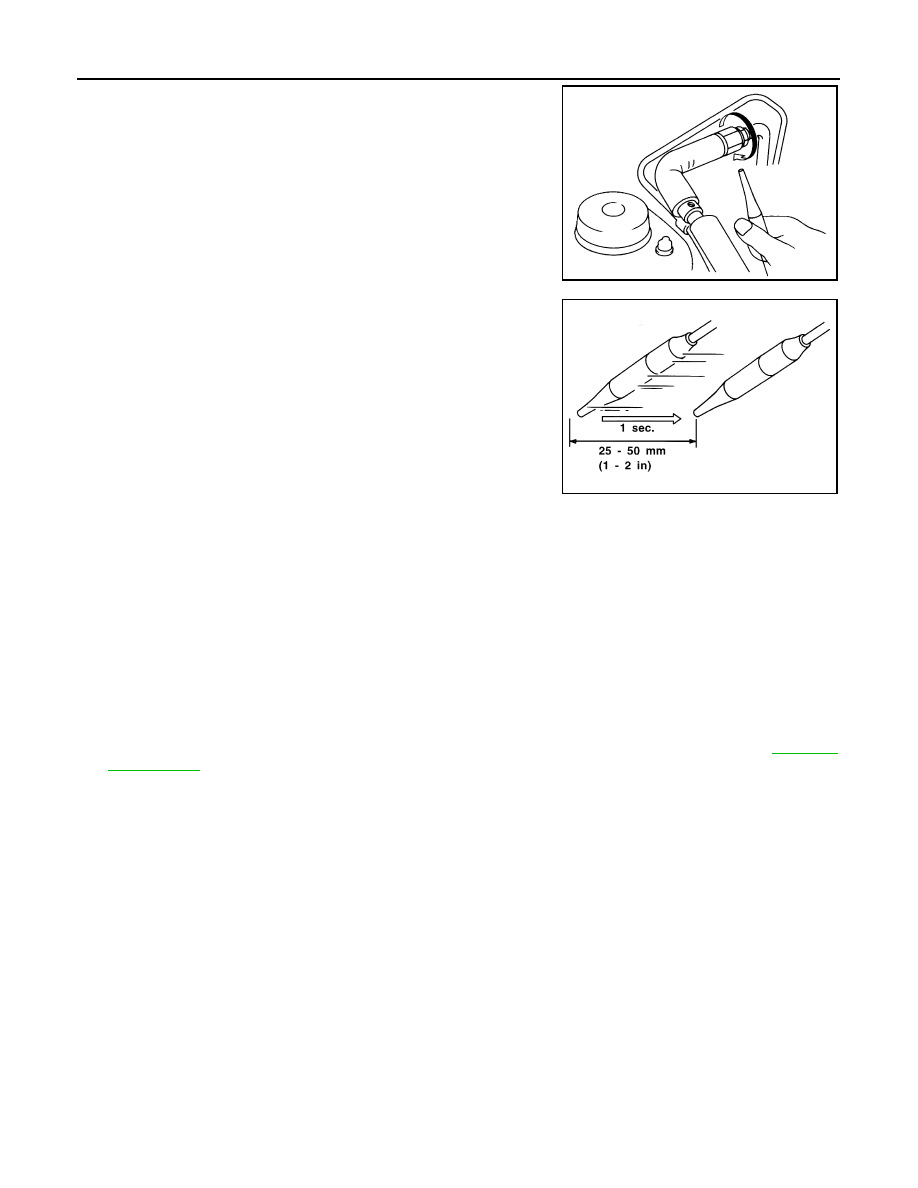
When testing, circle each fitting completely with probe.
3.
Move probe along component approximately 25 to 50 mm (1 to
2 in)/sec.
CHECKING PROCEDURE
To prevent inaccurate or false readings, make sure there is no refrigerant vapor, shop chemicals, or cigarette
smoke in the vicinity of the vehicle. Perform the leak test in calm area (low air/wind movement) so that the
leaking refrigerant is not dispersed.
1.
Stop the engine.
2.
Connect a suitable A/C manifold gauge set (SST: J-39183) to the A/C service valves.
3.
Check if the A/C refrigerant pressure is at least 345 kPa (3.52 kg/cm
2
, 50 psi) above 16
°
C (61
°
F). If less
than specification, recover/evacuate and recharge the system with the specified amount of refrigerant.
NOTE:
At temperatures below 16
°
C (61
°
F), leaks may not be detected since the system may not reach 345 kPa
(3.52 kg/cm
2
, 50 psi).
4.
Perform the leak test from the high-pressure side (compressor discharge a to evaporator inlet h) to the
low-pressure side [evaporator drain hose i to shaft seal o (VK45DE) or n (VQ35DE)]. Refer to
. Perform a leak check for the following areas carefully. Clean the component to be checked
and move the leak detected probe completely around the connection/component.
Compressor
Check the fitting of high- and low-pressure flexible hoses, relief valve and shaft seal.
Condenser
Check the fitting of high-pressure flexible hose and pipe, refrigerant pressure sensor.
Liquid tank
Check the fitting of refrigerant connection.
Service valves
Check all around the service valves. Ensure service valve caps are secured on the service valves (to pre-
vent leaks).
NOTE:
After removing A/C manifold gauge set from service valves, wipe any residue from valves to prevent any
false readings by leak detector.
Cooling unit (Evaporator)
With engine OFF, turn blower fan on “High” for at least 15 seconds to dissipate any refrigerant trace in the
cooling unit. Wait a minimum of 10 minutes accumulation time (refer to the manufacturer’s recommended
procedure for actual wait time) before inserting the leak detector probe into the drain hose.
Keep the probe inserted for at least 10 seconds. Use caution not to contaminate the probe tip with water
or dirt that may be in the drain hose.
5.
If a leak detector detects a leak, verify at least once by blowing compressed air into area of suspected
leak, then repeat check as outlined above.
SHA706E
SHA708EA
REFRIGERANT LINES
ATC-141
< SERVICE INFORMATION >
C
D
E
F
G
H
I
K
L
M
A
B
ATC
N
O
P
6.
Do not stop when one leak is found. Continue to check for additional leaks at all system components.
If no leaks are found, perform steps 7 - 10.
7.
Start the engine.
8.
Set the A/C control as follows;
a.
A/C switch: ON
b.
Mode door position: VENT (Ventilation)
c.
Intake position: Recirculation
d.
Temperature setting: Max. cold
e.
Fan speed: High
9.
Run engine at 1,500 rpm for at least 2 minutes.
10. Stop the engine and perform leak check again following steps 4
through 6 above.
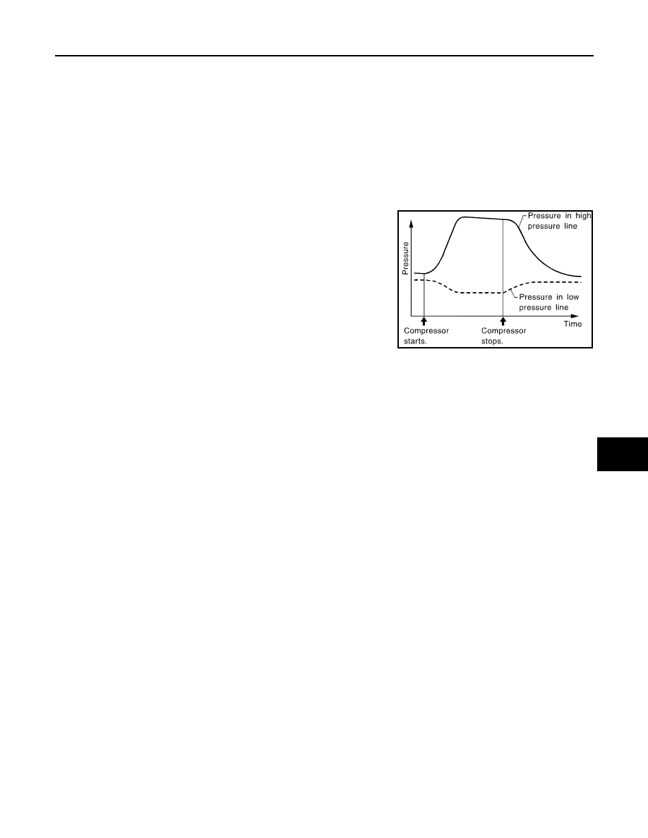
Refrigerant leaks should be checked immediately after stopping
the engine. Begin with the leak detector at the compressor. The
pressure on the high-pressure side will gradually drop after
refrigerant circulation stops and pressure on the low-pressure
side will gradually rise, as shown in the graph. Some leaks are
more easily detected when pressure is high.
11. Before connecting recovery/recycling recharging equipment to vehicle, check recovery/recycling recharg-
ing equipment gauges. No refrigerant pressure should be displayed. If pressure is displayed, recover
refrigerant from equipment lines and then check refrigerant purity.
12. Confirm refrigerant purity in supply tank using recovery/recycling recharging equipment and refrigerant
identifier.
13. Confirm refrigerant purity in vehicle A/C system using recovery/recycling recharging equipment and refrig-
erant identifier.
14. Discharge A/C system using approved refrigerant recovery equipment. Repair the leaking fitting or com-
ponent if necessary.
15. Evacuate and recharge A/C system and perform the leak test to confirm no refrigerant leaks.
16. Perform A/C performance test to ensure system works properly.
SHA839E
ATC-142
< SERVICE INFORMATION >
SERVICE DATA AND SPECIFICATIONS (SDS)
SERVICE DATA AND SPECIFICATIONS (SDS)
Compressor
INFOID:0000000001328235
Lubricant
INFOID:0000000001328236
Refrigerant
INFOID:0000000001328237
Engine Idling Speed
INFOID:0000000001328238
Refer to
EC-593, "Idle Speed and Ignition Timing"
EC-1196, "Idle Speed and Ignition Timing"
(VK45DE).
Belt Tension
INFOID:0000000001328239
(VQ35DE) or
(VK45DE).
Model
Calsonic Kansei make CWV-618
Type
V-6 variable displacement
Displacement
cm
3
(cu in)/rev
Max.
184 (11.228)
Min.
14.5 (0.885)
Cylinder bore
×
stroke
mm (in)
37 (1.46)
×
[2.3 - 28.6 (0.091 - 1.126)]
Direction of rotation
Clockwise (viewed from drive end)
Drive belt
Poly V
Model
Calsonic Kansei make CWV-618
Name
Nissan A/C System Oil Type S (DH-PS)
Capacity
m
(US fl oz, lmp fl oz)
Total in system
180 (6.0, 6.3)
Compressor (Service part) charging
amount
180 (6.0, 6.3)
Type
HFC-134a (R-134a)
Capacity
kg (lb)
0.55 (1.21)
AV-1
ELECTRICAL
C
D
E
F
G
H
I
J
L
M
SECTION
AV
A
B
AV
N
O
P
CONTENTS
AUDIO VISUAL, NAVIGATION & TELEPHONE SYS-
TEM
SERVICE INFORMATION . . . . . . .
PRECAUTIONS . . . . . . . . . . . . ...
PREPARATION . . . . . . . . . . . . ...
Commercial Service Tool . . . . . . . . . . ..
AUDIO . . . . . . . . . . . . . . . . .
System Description . . . . . . . . . . . . ...
Component Parts Location . . . . . . . . . ....
Schematic - AUDIO - / with Navigation System . ....
Wiring Diagram - AUDIO - / with Navigation Sys-
tem . . . . . . . . . . . . . . . . . . ....
Schematic - AUDIO - without Navigation System .
Wiring Diagram - AUDIO - / without Navigation
System . . . . . . . . . . . . . . . . .
Terminal and Reference Value for Audio Unit . . .
Terminal and Reference Value for BOSE Speaker
Amp . . . . . . . . . . . . . . . . . . .
Terminal and Reference Value for A/C and AV
Switch . . . . . . . . . . . . . . . . . ..
Terminal and Reference Value for Woofer . . . ..
Terminal and Reference Value for Satellite Radio
Tuner . . . . . . . . . . . . . . . . . ...
A/C and AV Switch Self-Diagnosis Function . . ...
Trouble Diagnosis . . . . . . . . . . . . ...
Power Supply Circuit Inspection . . . . . . . .
Audio Steering Wheel Switch Inspection . . . .
A/C and AV Switch Inspection . . . . . . . .
BOSE Speaker Amp. Inspection . . . . . . . .
Vehicle Speed Signal Inspection . . . . . . . .
Locking CD Auto-Changer Mechanism . . . . ...
Removal and Installation of Audio Unit . . . . ...
Disassembly and Assembly of Audio Unit . . . ...
Removal and Installation for A/C and AV Switch .
Removal and Installation for Front Door Speaker .
Removal and Installation for Rear Door Speaker ....
Removal and Installation for Instrument Speaker .
Removal and Installation for Tweeter . . . . . ..
Removal and Installation for Woofer (BOSE Sys-
tem) . . . . . . . . . . . . . . . . . . .
Removal and Installation for BOSE Speaker Amp .
Removal and Installation of Satellite Radio Tuner .
Removal and Installation of Satellite Radio Anten-
na . . . . . . . . . . . . . . . . . . . .
ANTENNA . . . . . . . . . . . . . . .
System Description . . . . . . . . . . . . ..
Wiring Diagram - M/ANT - . . . . . . . . . ...
Terminal and Reference Value for Audio Unit . . .
Antenna Amp. Inspection . . . . . . . . . .
Location of Antenna . . . . . . . . . . . . .
Window Antenna Repair . . . . . . . . . . ..
Removal and Installation of Roof Antenna . . . ..
Removal and Installation of Satellite Radio Anten-
na . . . . . . . . . . . . . . . . . . . .
INTEGRATED DISPLAY SYSTEM . . . . ...
System Description . . . . . . . . . . . . ..
Component Description . . . . . . . . . . ...
CAN Communication Unit . . . . . . . . . .
Component Parts Location . . . . . . . . . ..
Schematic - INF/D - . . . . . . . . . . . . .
Wiring Diagram - INF/D - . . . . . . . . . . .
Schematic - COMM - . . . . . . . . . . . ...
Wiring Diagram - COMM - . . . . . . . . . ...
Terminal and Reference Value for Display Control
Unit . . . . . . . . . . . . . . . . . . ..
Terminal and Reference Value for Display . . . ..
Terminal and Reference Value for A/C and AV
Switch . . . . . . . . . . . . . . . . . ..
Special Note for Trouble Diagnosis . . . . . . .
On Board Self-Diagnosis Function . . . . . . ..
Self-Diagnosis Mode (DCU) . . . . . . . . .
Confirmation/Adjustment Mode . . . . . . . ...
CAN Diagnostic Support Monitor . . . . . . . .
A/C and AV Switch Self-Diagnosis Function . . ...
Нет комментариевНе стесняйтесь поделиться с нами вашим ценным мнением.
Текст