Infiniti FX35 / FX45. Manual — part 816

INTERIOR ROOM LAMP
LT-159
< SERVICE INFORMATION >
C
D
E
F
G
H
I
J
L
M
A
B
LT
N
O
P
1.
Select “INT LAMP” of BCM data monitor item.
2.
Check that switches listed in display item list turn ON-OFF linked with switch operation. Refer to
for switches and their functions.
OK or NG
OK
>> GO TO 2.
NG
>> Inspect malfunctioning switch system.
2.
CHECK BETWEEN BCM AND MAP LAMP
CONSULT-III ACTIVE TEST
1.
Select “INT LAMP” of BCM (INT LAMP) active test item.
2.
With operating the test item, check the map lamp operation (When map lamp switch is in DOOR position).
OK or NG
OK
>> Replace BCM. Refer to
BCS-13, "Removal and Installation of BCM"
.
NG
>> GO TO 3.
3.
CHECK MAP LAMP INPUT
1.
Turn ignition switch OFF.
2.
Check voltage between map lamp harness connector R52 termi-
nal 2 and ground.
OK or NG
OK
>> GO TO 6.
NG
>> GO TO 4.
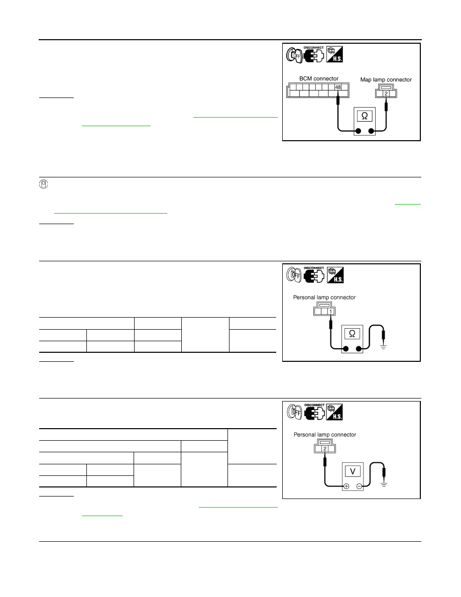
4.
CHECK MAP LAMP
1.
Disconnect map lamp connector.
2.
Check continuity between map lamp.
OK or NG
OK
>> GO TO 5.
NG
>> Replace Map lamp.
5.
CHECK MAP LAMP CIRCUIT
1.
Disconnect BCM connector.
2.
Check continuity between BCM harness connector M4 terminal
41 and map lamp harness connector R52 terminal 3.
OK or NG
OK
>> Replace BCM if map lamp does not work after setting
the connector again. Refer to
.
NG
>> Repair harness or connector.
6.
CHECK MAP LAMP CIRCUIT
Map lamp should operate.
2 – Ground
: Battery voltage.
PKIA5253E
Map lamp
Condition
Continuity
2
3
Map lamp switch is DOOR.
Yes
Map lamp switch is OFF.
No
PKIA6054E
41 – 3
: Continuity should exist.
PKIB3515E
LT-160
< SERVICE INFORMATION >
INTERIOR ROOM LAMP
1.
Disconnect BCM connector and map lamp connector.
2.
Check continuity between BCM harness connector M4 terminal
48 and map lamp harness connector R52 terminal 2.
OK or NG
OK
>> Replace BCM if map lamp does not work after setting
the connector again. Refer to
.
NG
>> Repair harness or connector.
Personal Lamp Control Does Not Operate
INFOID:0000000001381758
1.
CHECK REAR DOOR SWITCH
CONSULT-III DATA MONITOR
1.
Select “INT LAMP” of BCM data monitor item.
2.
Check that switches listed in display item list turn ON-OFF linked with switch operation. Refer to
for switches and their functions.
OK or NG
OK
>> GO TO 2.
NG
>> Inspect malfunctioning rear door switch.
2.
CHECK PERSONAL LAMP CIRCUIT
1.
Turn ignition switch OFF.
2.
Disconnect personal lamp connector.
3.
Open rear door.
4.
Check continuity between personal lamp (RH and LH) harness
connectors and ground.
OK or NG
OK
>> GO TO 3.
NG
>> Repair harness or connector.
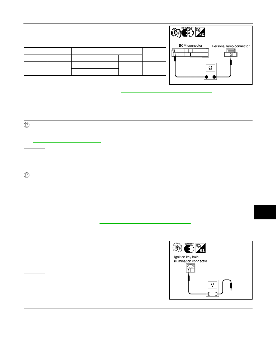
3.
CHECK PERSONAL LAMP INPUT
Check voltage between personal lamp harness connector and
ground.
OK or NG
OK
>> Replace personal lamp. Refer to
NG
>> GO TO 4.
4.
CHECK PERSONAL LAMP CIRCUIT
48 – 2
: Continuity should exist.
PKIB3514E
Personal lamp connector
Terminal
Ground
Continuity
RH
R55
1
Yes
LH
R54
1
PKIA5257E
Terminals
Voltage
(Approx.)
(+)
(-)
Personal lamp connector
Terminal
Ground
RH
R55
2
Battery voltage
LH
R54
PKIA5258E
INTERIOR ROOM LAMP
LT-161
< SERVICE INFORMATION >
C
D
E
F
G
H
I
J
L
M
A
B
LT
N
O
P
1.
Disconnect BCM connector.
2.
Check continuity between BCM harness connector and personal
lamp (RH and LH) harness connectors.
OK or NG
OK
>> Replace BCM if personal lamp does not work after set-
ting the connector again. Refer to
BCS-13, "Removal and Installation of BCM"
NG
>> Repair harness or connector.
Ignition Keyhole Illumination Control Does Not Operate
INFOID:0000000001381759
1.
CHECK EACH SWITCH
CONSULT-III DATA MONITOR
1.
Select “INT LAMP” of BCM data monitor item.
2.
Check that switches listed in display item list turn ON-OFF linked with switch operation. Refer to
for switches and their functions.
OK or NG
OK
>> GO TO 2.
NG
>> Inspect malfunctioning switch system.
2.
ACTIVE TEST
CONSULT-III ACTIVE TEST
1.
Select “IGN ILLUM” of BCM (INT LAMP) active test item.
2.
With operating the test item, check the ignition key hole illumination operation (When interior room lamp
switch is in DOOR position).
OK or NG
OK
>> Replace BCM. Refer to
BCS-13, "Removal and Installation of BCM"
.
NG
>> GO TO 3.
3.
CHECK IGNITION KEY HOLE ILLUMINATION INPUT
1.
Turn ignition switch OFF.
2.
Check voltage between ignition key hole illumination harness
connector M24 terminal 1 and ground.
OK or NG
OK
>> GO TO 4.
NG
>> GO TO 6.
4.
CHECK IGNITION KEY HOLE ILLUMINATION BULB
BCM
Personal lamp
Continuity
Connector
Terminal
Connector
Terminal
M4
41
RH
R55
2
Yes
LH
R54
PKIB3517E
Ignition key hole illumination
should operate.
1 – Ground
: Battery voltage.
PKIA5260E
LT-162
< SERVICE INFORMATION >
INTERIOR ROOM LAMP
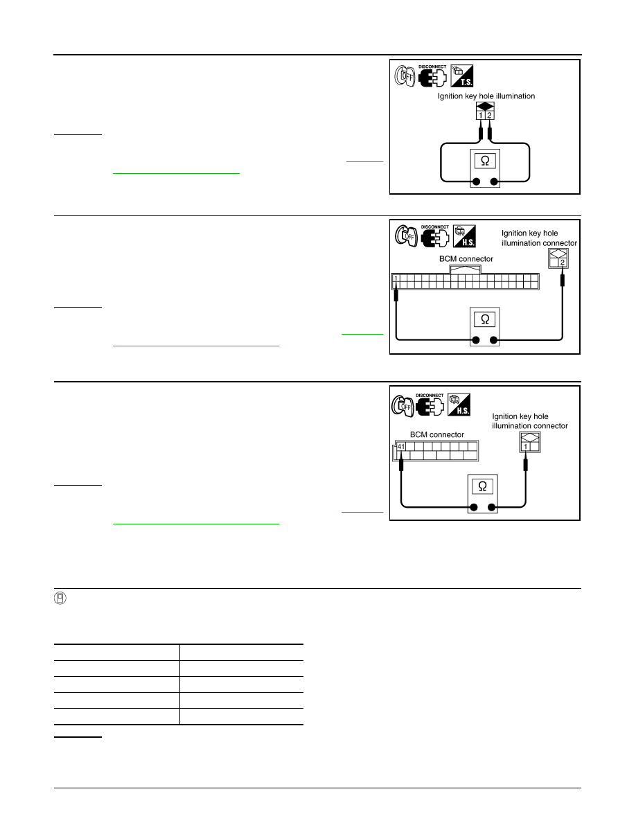
1.
Disconnect ignition key hole illumination connector.
2.
Check continuity between ignition key hole illumination terminals
1 and 2.
OK or NG
OK
>> GO TO 5.
NG
>> Replace ignition key hole illumination. Refer to
.
5.
CHECK IGNITION KEY HOLE ILLUMINATION CIRCUIT
1.
Disconnect BCM connector.
2.
Check continuity between BCM harness connector M3 terminal
1 and ignition key hole illumination harness connector M24 ter-
minal 2.
OK or NG
OK
>> Replace BCM if ignition key hole illumination does not
work after setting the connector again. Refer to
"Removal and Installation of BCM"
NG
>> Repair harness or connector.
6.
CHECK IGNITION KEY HOLE ILLUMINATION CIRCUIT
1.
Disconnect BCM connector and ignition key hole illumination
connector.
2.
Check continuity between BCM harness connector M4 terminal
41 and ignition key hole illumination harness connector M24 ter-
minal 1.
OK or NG
OK
>> Replace BCM if ignition key hole illumination does not
work after setting the connector again. Refer to
"Removal and Installation of BCM"
NG
>> Repair harness or connector.
All Step Lamps Do Not Operate
INFOID:0000000001381760
1.
CHECK EACH DOOR SWITCH
CONSULT-III DATA MONITOR
1.
Select “INT LAMP” of BCM data monitor item.
2.
Check that switches listed in display item list turn ON-OFF linked with switch operation.
OK or NG
OK
>> GO TO 2.
NG
>> Inspect malfunctioning switch system.
2.
CHECK STEP LAMP INPUT
1 – 2
: Continuity should exist.
PKIA7789E
1 – 2
: Continuity should exist.
PKIA7643E
41 – 1
: Continuity should exist.
PKIB3520E
Switch name
CONSULT screen
Driver side door switch
DOOR SW - DR
Passenger side door switch
DOOR SW - AS
Rear RH side door switch
DOOR SW - RR
Rear LH side door switch
DOOR SW - RL
Нет комментариевНе стесняйтесь поделиться с нами вашим ценным мнением.
Текст