Infiniti FX35 / FX45. Manual — part 347
DTC P0011, P0021 IVT CONTROL
EC-149
< SERVICE INFORMATION >
[VQ35DE]
C
D
E
F
G
H
I
J
K
L
M
A
EC
N
P
O
DTC P0011, P0021 IVT CONTROL
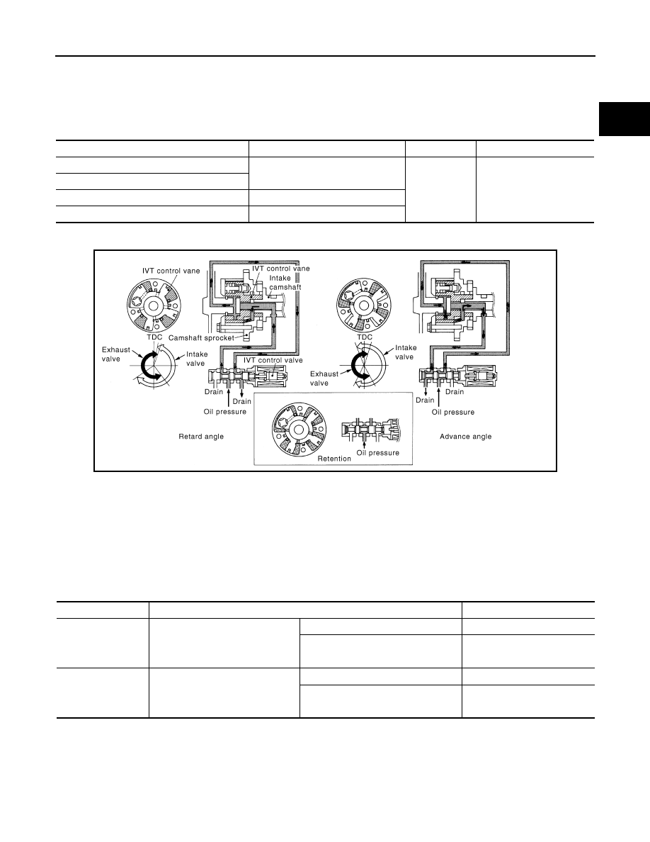
Description
INFOID:0000000001325958
SYSTEM DESCRIPTION
*: This signal is sent to the ECM through CAN communication line
This mechanism hydraulically controls cam phases continuously with the fixed operating angle of the intake
valve.
The ECM receives signals such as crankshaft position, camshaft position, engine speed, and engine coolant
temperature. Then, the ECM sends ON/OFF pulse duty signals to the intake valve timing control solenoid
valve depending on driving status. This makes it possible to control the shut/open timing of the intake valve to
increase engine torque in low/mid speed range and output in high-speed range.
CONSULT-III Reference Value in Data Monitor Mode
INFOID:0000000001325959
Specification data are reference values.
Sensor
Input signal to ECM
ECM function
Actuator
Crankshaft position sensor (POS)
Engine speed and piston position
Intake valve
timing control
Intake valve timing control
solenoid valve
Camshaft position sensor (PHASE)
Engine coolant temperature sensor
Engine coolant temperature
Wheel sensor
Vehicle speed*
PBIB3276E
MONITOR ITEM
CONDITION
SPECIFICATION
INT/V TIM(B1)
INT/V TIM(B2)
• Engine: After warming up
• Selector lever: P or N
• Air conditioner switch: OFF
• No load
Idle
−
5
°
- 5
°
CA
When revving engine up to 2,000 rpm
quickly
Approx. 0
°
- 30
°
CA
INT/V SOL(B1)
INT/V SOL(B2)
• Engine: After warming up
• Selector lever: P or N
• Air conditioner switch: OFF
• No load
Idle
0% - 2%
When revving engine up to 2,000 rpm
quickly
Approx. 0% - 50%
EC-150
< SERVICE INFORMATION >
[VQ35DE]
DTC P0011, P0021 IVT CONTROL
On Board Diagnosis Logic
INFOID:0000000001325960
FAIL-SAFE MODE
When the malfunction is detected, the ECM enters fail-safe mode.
DTC Confirmation Procedure
INFOID:0000000001325961
CAUTION:
Always drive at a safe speed.
NOTE:
• If DTC P0011 or P0021 is displayed with DTC P0075 or P0081, first perform trouble diagnosis for DTC
P0075 or P0081. Refer to
• If DTC Confirmation Procedure has been previously conducted, always turn ignition switch OFF and wait at
least 10 seconds before conducting the next test.
TESTING CONDITION:
Before performing the following procedure, confirm that battery voltage is between 10V and 16V at
idle.
WITH CONSULT-III
1.
Turn ignition switch ON and select “DATA MONITOR” mode with CONSULT-III.
2.
Start engine and warm it up to the normal operating temperature.
3.
Maintain the following conditions for at least 6 consecutive seconds. Hold the accelerator pedal as steady
as possible.
4.
Let engine idle for 10 seconds.
5.
Check 1st trip DTC.
6.
If 1st trip DTC is detected, go to
If 1st trip DTC is not detected, go to next step.
7.
Maintain the following conditions for at least 20 consecutive seconds.
DTC No.
Trouble diagnosis
name
Detecting condition
Possible cause
P0011
0011
(Bank 1)
Intake valve timing
control performance
There is a gap between angle of target and
phase-control angle degree.
• Crankshaft position sensor (POS)
• Camshaft position sensor (PHASE)
• Intake valve control solenoid valve
• Accumulation of debris to the signal pick-up
portion of the camshaft
• Timing chain installation
• Foreign matter caught in the oil groove for in-
take valve timing control
P0021
0021
(Bank 2)
Detected items
Engine operating condition in fail-safe mode
Intake valve timing control
The signal is not energized to the solenoid valve and the valve control does not function.
VHCL SPEED SE
100 - 120 km/h (63 - 75 MPH)
ENG SPEED
1,200 - 2,000 rpm
COOLAN TEMP/S
More than 60
°
C (140
°
F)
B/FUEL SCHDL
More than 7.26 msec
Selector lever
D position
ENG SPEED
1,700 - 3,175 rpm (A constant rotation is maintained.)
COOLAN TEMP/S
More than 70
°
C (158
°
F)
Selector lever
1st or 2nd position
Driving location uphill
Driving vehicle uphill
(Increased engine load will help maintain the driving
conditions required for this test.)
DTC P0011, P0021 IVT CONTROL
EC-151
< SERVICE INFORMATION >
[VQ35DE]
C
D
E
F
G
H
I
J
K
L
M
A
EC
N
P
O
8.
Check 1st trip DTC.
9.
If 1st trip DTC is detected, go to
WITH GST
Follow the procedure “WITH CONSULT-III” above.
Diagnosis Procedure
INFOID:0000000001325962
1.
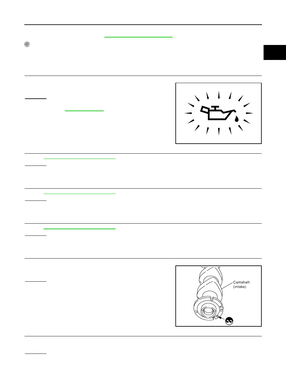
CHECK OIL PRESSURE WARNING LAMP
1.
Start engine.
2.
Check oil pressure warning lamp and confirm it is not illumi-
nated.
OK or NG
OK
>> GO TO 2.
NG
>> Go to
.
2.
CHECK INTAKE VALVE TIMING CONTROL SOLENOID VALVE
EC-152, "Component Inspection"
OK or NG
OK
>> GO TO 3.
NG
>> Replace malfunctioning intake valve timing control solenoid valve.
3.
CHECK CRANKSHAFT POSITION SENSOR (POS)
EC-323, "Component Inspection"
OK or NG
OK
>> GO TO 4.
NG
>> Replace crankshaft position sensor (POS).
4.
CHECK CAMSHAFT POSITION SENSOR (PHASE)
EC-330, "Component Inspection"
OK or NG
OK
>> GO TO 5.
NG
>> Replace malfunctioning camshaft position sensor (PHASE).
5.
CHECK CAMSHAFT (INT)
Check the following.
• Accumulation of debris to the signal plate of camshaft rear end
• Chipping signal plate of camshaft rear end
OK or NG
OK
>> GO TO 6.
NG
>> Remove debris and clean the signal plate of camshaft
rear end or replace camshaft.
6.
CHECK TIMING CHAIN INSTALLATION
Check service records for any recent repairs that may cause timing chain misaligned.
Are there any service records that may cause timing chain misaligned?
Yes or No
PBIA8559J
SEC905C
EC-152
< SERVICE INFORMATION >
[VQ35DE]
DTC P0011, P0021 IVT CONTROL
Yes
>> Check timing chain installation. Refer to
.
No
>> GO TO 7.
7.
CHECK LUBRICATION CIRCUIT
EM-65, "Removal and Installation"
.
OK or NG
OK
>> GO TO 8.
NG
>> Clean lubrication line.
8.
CHECK INTERMITTENT INCIDENT
for CMP sensor (PHASE).
>> INSPECTION END
Component Inspection
INFOID:0000000001325963
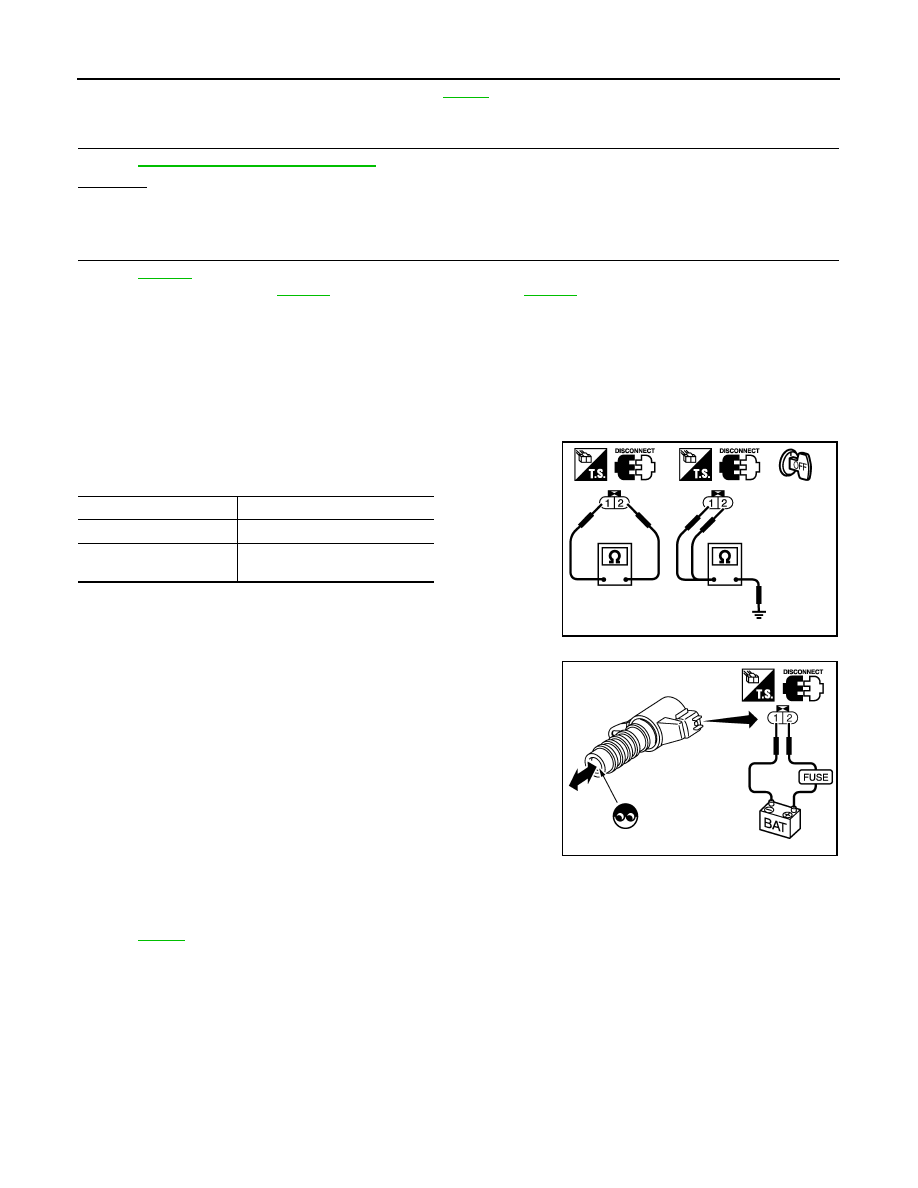
INTAKE VALVE TIMING CONTROL SOLENOID VALVE
1.
Disconnect intake valve timing control solenoid valve harness connector.
2.
Check resistance between intake valve timing control solenoid
valve as follows.
If NG, replace intake valve timing control solenoid valve.
If OK, go to next step.
3.
Remove intake valve timing control solenoid valve.
4.
Provide 12V DC between intake valve timing control solenoid
valve terminals and then interrupt it. Make sure that the plunger
moves as shown in the figure.
CAUTION:
Do not apply 12V DC continuously for 5 seconds or more.
Doing so may result in damage to the coil in intake valve
timing control solenoid valve.
If NG, replace intake valve timing control solenoid valve.
NOTE:
Always replace O-ring when intake valve timing control
solenoid valve is removed.
Removal and Installation
INFOID:0000000001325964
INTAKE VALVE TIMING CONTROL SOLENOID VALVE
Terminal
Resistance
1 and 2
7.0 - 7.5
Ω
[at 20
°
C (68
°
F)]
1 or 2 and ground
∞Ω
(Continuity should not exist.)
PBIB0193E
PBIB2275E
Нет комментариевНе стесняйтесь поделиться с нами вашим ценным мнением.
Текст