Infiniti FX35 / FX45. Manual — part 492

DTC P0011, P0021 IVT CONTROL
EC-729
< SERVICE INFORMATION >
[VK45DE]
C
D
E
F
G
H
I
J
K
L
M
A
EC
N
P
O
• If DTC Confirmation Procedure has been previously conducted, always turn ignition switch OFF and wait at
least 10 seconds before conducting the next test.
TESTING CONDITION:
Before performing the following procedure, confirm that battery voltage is between 10V and 16V at
idle.
PROCEDURE FOR MALFUNCTION A
With CONSULT-III
1.
Turn ignition switch ON.
2.
Select “DATA MONITOR” mode with CONSULT-III.
3.
Maintain the following conditions for at least 10 consecutive seconds.
4.
Maintain the following conditions for at least 20 consecutive seconds.
5.
Check 1st trip DTC.
6.
If 1st trip DTC is detected, go to
With GST
Follow the procedure “With CONSULT-III” above.
PROCEDURE FOR MALFUNCTION B
With CONSULT-III
1.
Turn ignition switch ON.
2.
Select “DATA MONITOR” mode with CONSULT-III.
3.
Maintain the following conditions for at least 10 consecutive seconds.
4.
Check 1st trip DTC.
5.
If 1st trip DTC is detected, go to
With GST
Follow the procedure “With CONSULT-III” above.
ENG SPEED
More than 2,000 rpm (A constant rotation is maintained.)
COOLAN TEMP/S
More than 70
°
C (158
°
F)
Selector lever
1st or 2nd position
Driving location uphill
Driving vehicle uphill
(Increased engine load will help maintain the driving conditions
required for this test.)
ENG SPEED
Idle
COOLAN TEMP/S
More than 70
°
C (158
°
F)
Selector lever
P or N position
ENG SPEED
1,700 - 3,175 rpm (A constant rotation is maintained.)
COOLAN TEMP/S
70 - 105
°
C (158 - 221
°
F)
Selector lever
1st or 2nd position
Driving location uphill
Driving vehicle uphill
(Increased engine load will help maintain the driving conditions
required for this test.)
EC-730
< SERVICE INFORMATION >
[VK45DE]
DTC P0011, P0021 IVT CONTROL
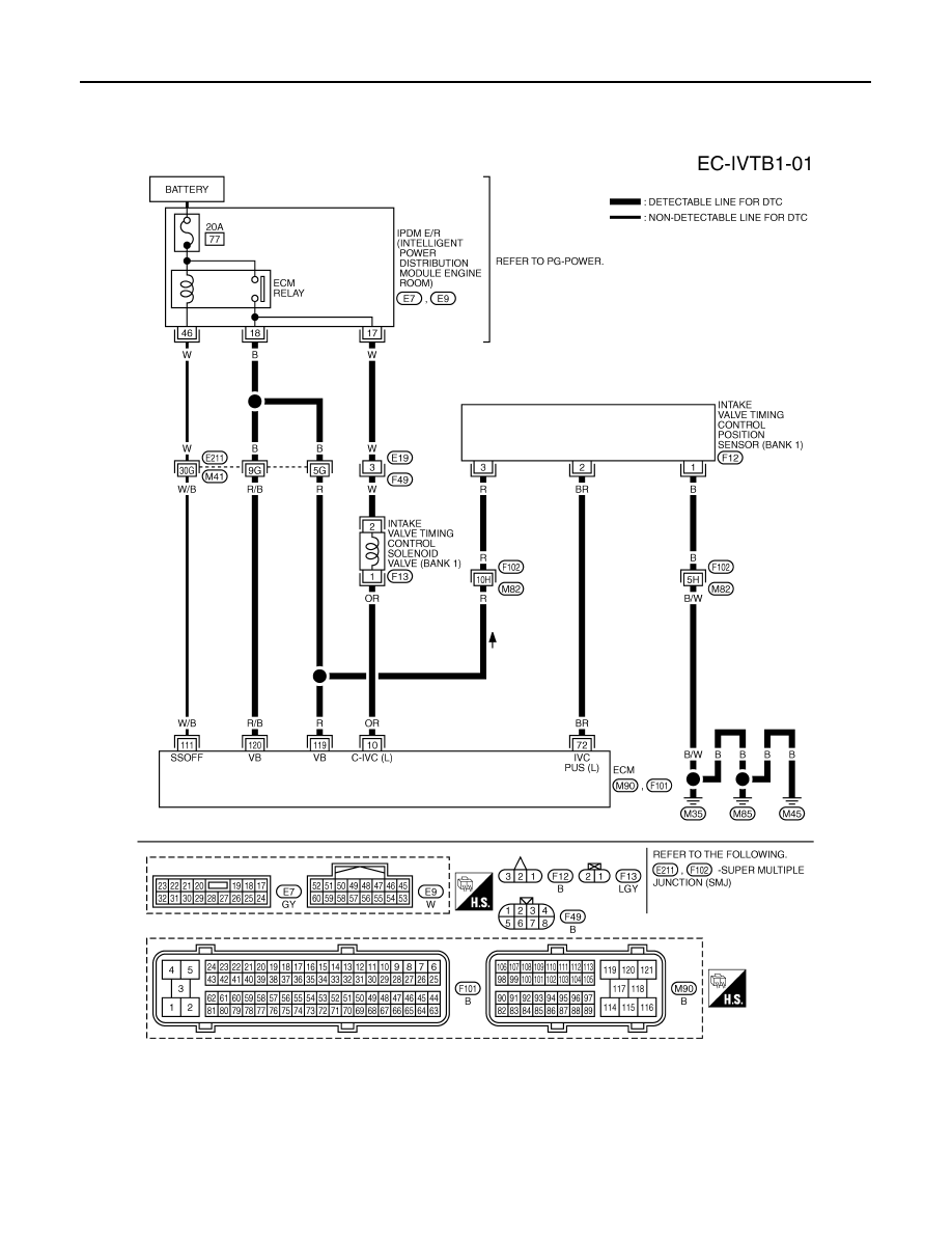
Wiring Diagram
INFOID:0000000001326558
BANK 1
Specification data are reference values and are measured between each terminal and ground.
Pulse signal is measured by CONSULT-III.
CAUTION:
TBWM1323E

DTC P0011, P0021 IVT CONTROL
EC-731
< SERVICE INFORMATION >
[VK45DE]
C
D
E
F
G
H
I
J
K
L
M
A
EC
N
P
O
Do not use ECM ground terminals when measuring input/output voltage. Doing so may result in dam-
age to the ECM's transistor. Use a ground other than ECM terminals, such as the ground.
: Average voltage for pulse signal (Actual pulse signal can be confirmed by oscilloscope.)
TER-
MI-
NAL
NO.
WIRE
COLOR
ITEM
CONDITION
DATA (DC Voltage)
10
OR
Intake valve timing control
solenoid valve (Bank 1)
[Engine is running]
• Warm-up condition
• Idle speed
BATTERY VOLTAGE
(11 - 14V)
[Engine is running]
• Warm-up condition
• Engine speed: 2,000rpm
7 - 12V
72
BR
Intake valve timing control
position sensor (Bank 1)
[Engine is running]
• Warm-up condition
• Idle speed
0 - 1.0V
[Engine is running]
• Engine speed: 2,000rpm
0 - 1.0V
111
W/B
ECM relay
(Self shut-off)
[Engine is running]
[Ignition switch: OFF]
• For a few seconds after turning ignition
switch OFF
0 - 1.5V
[Ignition switch: OFF]
• More than a few seconds after turning igni-
tion switch OFF
BATTERY VOLTAGE
(11 - 14V)
119
120
R
R/B
Power supply for ECM
[Ignition switch: ON]
BATTERY VOLTAGE
(11 - 14V)
PBIB1790E
PBIB2046E
EC-732
< SERVICE INFORMATION >
[VK45DE]
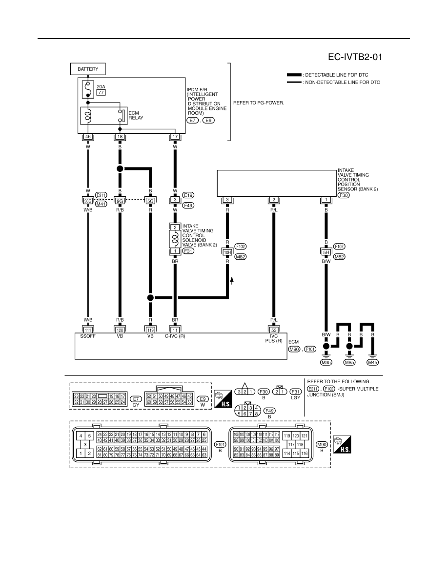
DTC P0011, P0021 IVT CONTROL
BANK 2
Specification data are reference values and are measured between each terminal and ground.
Pulse signal is measured by CONSULT-III.
CAUTION:
Do not use ECM ground terminals when measuring input/output voltage. Doing so may result in dam-
age to the ECM's transistor. Use a ground other than ECM terminals, such as the ground.
TBWM1324E
Нет комментариевНе стесняйтесь поделиться с нами вашим ценным мнением.
Текст