Infiniti FX35, FX50 (S51). Manual — part 821

P0137, P0157 HO2S2
EC-825
< DTC/CIRCUIT DIAGNOSIS >
[VK50VE]
C
D
E
F
G
H
I
J
K
L
M
A
EC
N
P
O
Is the inspection result normal?
YES
>> INSPECTION END
NO
>> GO TO 5.
5.
CHECK HEATED OXYGEN SENSOR 2-III
Check the voltage between ECM harness connector terminals under the following conditions.
Is the inspection result normal?
YES
>> INSPECTION END
NO
>> GO TO 6.
6.
REPLACE HEATED OXYGEN SENSOR 2
Replace malfunctioning heated oxygen sensor 2.
CAUTION:
• Discard any heated oxygen sensor which has been dropped from a height of more than 0.5 m (19.7
in) onto a hard surface such as a concrete floor; use a new one.
• Before installing new oxygen sensor, clean exhaust system threads using Oxygen Sensor Thread
Cleaner [commercial service tool (J-43897-18 or J-43897-12)] and approved anti-seize lubricant
(commercial service tool).
>> INSPECTION END
ECM
Condition
Voltage
Connector
+
–
Terminal
Terminal
F110
32
[HO2S2
(bank 1)]
31
Coasting from 80 km/h (50 MPH) with se-
lector lever in the D position
The voltage should be above 0.74 V at
least once during this procedure.
The voltage should be below 0.18 V at
least once during this procedure.
36
[HO2S2
(bank 2)]
EC-826
< DTC/CIRCUIT DIAGNOSIS >
[VK50VE]
P0138, P0158 HO2S2
P0138, P0158 HO2S2
Description
INFOID:0000000005237309
The heated oxygen sensor 2, after three way catalyst (manifold),
monitors the oxygen level in the exhaust gas on each bank.
Even if switching characteristics of the air fuel ratio (A/F) sensor 1
are shifted, the air fuel ratio is controlled to stoichiometric, by the sig-
nal from the heated oxygen sensor 2.
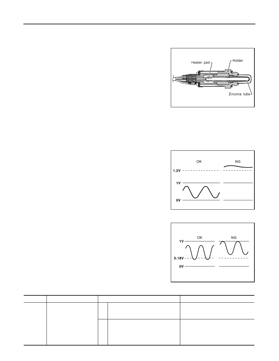
This sensor is made of ceramic zirconia. The zirconia generates volt-
age from approximately 1 V in richer conditions to 0 V in leaner con-
ditions.
Under normal conditions the heated oxygen sensor 2 is not used for
engine control operation.
DTC Logic
INFOID:0000000005237310
DTC DETECTION LOGIC
The heated oxygen sensor 2 has a much longer switching time between rich and lean than the air fuel ratio (A/
F) sensor 1. The oxygen storage capacity of the three way catalyst (manifold) causes the longer switching
time.
MALFUNCTION A
To judge the malfunctions of heated oxygen sensor 2, ECM monitors
whether the voltage is unusually high during various driving condi-
tions such as fuel cut.
MALFUNCTION B
To judge the malfunctions of heated oxygen sensor 2, ECM monitors
whether the minimum voltage of sensor is sufficiently low during var-
ious driving conditions such as fuel cut.
SEF327R
PBIB1848E
PBIB2376E
DTC No.
Trouble diagnosis name
DTC detecting condition
Possible cause
P0138
Heated oxygen sensor 2
(bank 1) circuit high voltage
A)
An excessively high voltage from the
sensor is sent to ECM.
• Harness or connectors
(The sensor circuit is open or shorted)
• Heated oxygen sensor 2
B)
The minimum voltage from the sensor is
not reached to the specified voltage.
• Harness or connectors
(The sensor circuit is open or shorted)
• Heated oxygen sensor 2
• Fuel pressure
• Fuel injector

P0138, P0158 HO2S2
EC-827
< DTC/CIRCUIT DIAGNOSIS >
[VK50VE]
C
D
E
F
G
H
I
J
K
L
M
A
EC
N
P
O
DTC CONFIRMATION PROCEDURE
1.
PRECONDITIONING
If DTC Confirmation Procedure has been previously conducted, always perform the following procedure
before conducting the next test.
1.
Turn ignition switch OFF and wait at least 10 seconds.
2.
Turn ignition switch ON.
3.
Turn ignition switch OFF and wait at least 10 seconds.
>> GO TO 2.
2.
PERFORM DTC CONFIRMATION PROCEDURE FOR MALFUNCTION A
1.
Start engine and warm it up to the normal operating temperature.
2.
Turn ignition switch OFF and wait at least 10 seconds.
3.
Turn ignition switch ON.
4.
Turn ignition switch OFF and wait at least 10 seconds.
5.
Start engine and keep the engine speed between 3,500 and 4,000 rpm for at least 1 minute under no load.
6.
Let engine idle for 2 minutes.
7.
Check 1st trip DTC.
Is 1st trip DTC detected?
YES
>> Go to
NO-1
>> With CONSULT-III: GO TO 3.
NO-2
>> With GST: GO TO 5.
3.
PERFORM DTC CONFIRMATION PROCEDURE FOR MALFUNCTION B
With CONSULT-III
NOTE:
For better results, perform “DTC WORK SUPPORT” at a temperature of 0 to 30
°
C (32 to 86
°
F).
1.
Start engine and warm it up to the normal operating temperature.
2.
Turn ignition switch OFF and wait at least 10 seconds.
3.
Turn ignition switch ON.
4.
Turn ignition switch OFF and wait at least 10 seconds.
5.
Start engine and keep the engine speed between 3,500 and 4,000 rpm for at least 1 minute under no load.
6.
Let engine idle for 1 minute.
7.
Select “DATA MONITOR” mode with CONSULT-III.
8.
Check that “COOLAN TEMP/S” indicates more than 70
°
C (158
°
F).
If not, warm up engine and go to next step when “COOLAN TEMP/S” indication reaches 70
°
C (158
°
F).
9.
Open engine hood.
10. Select “HO2S2 (B1) P1146” (for DTC P0138) or “HO2S2 (B2) P1166” (for DTC P0158) of “HO2S2” in
“DTC WORK SUPPORT” mode with CONSULT-III.
11. Follow the instruction of CONSULT-III display.
NOTE:
It will take at most 10 minutes until “COMPLETED” is displayed.
12. Touch “SELF-DIAG RESULTS”.
Which is displayed on CONSULT-III screen?
OK
>> INSPECTION END
NG
>> Go to
CON NOT BE DIAGNOSED>>GO TO 4.
P0158
Heated oxygen sensor 2
(bank 2) circuit high voltage
A)
An excessively high voltage from the
sensor is sent to ECM.
• Harness or connectors
(The sensor circuit is open or shorted)
• Heated oxygen sensor 2
B)
The minimum voltage from the sensor is
not reached to the specified voltage.
• Harness or connectors
(The sensor circuit is open or shorted)
• Heated oxygen sensor 2
• Fuel pressure
• Fuel injector
DTC No.
Trouble diagnosis name
DTC detecting condition
Possible cause

EC-828
< DTC/CIRCUIT DIAGNOSIS >
[VK50VE]
P0138, P0158 HO2S2
4.
PERFORM DTC CONFIRMATION PROCEDURE FOR MALFUNCTION B AGAIN
1.
Turn ignition switch OFF and leave the vehicle in a cool place (soak the vehicle).
2.
Perform DTC confirmation procedure again.
>> GO TO 3.
5.
PERFORM COMPONENT FUNCTION CHECK FOR MALFUNCTION B
With GST
Perform component function check. Refer to
EC-828, "Component Function Check"
NOTE:
Use component function check to check the overall function of the heated oxygen sensor 2 circuit. During this
check, a 1st trip DTC might not be confirmed.
Is the inspection result normal?
YES
>> INSPECTION END
NO
>> Go to
Component Function Check
INFOID:0000000005237311
1.
PERFORM COMPONENT FUNCTION CHECK-I
With GST
1.
Start engine and warm it up to the normal operating temperature.
2.
Turn ignition switch OFF and wait at least 10 seconds.
3.
Turn ignition switch ON.
4.
Turn ignition switch OFF and wait at least 10 seconds.
5.
Start engine and keep the engine speed between 3,500 and 4,000 rpm for at least 1 minute under no load.
6.
Let engine idle for 1 minute.
7.
Check the voltage between ECM harness connector terminals under the following conditions.
Is the inspection result normal?
YES
>> INSPECTION END
NO
>> GO TO 2.
2.
PERFORM COMPONENT FUNCTION CHECK-II
Check the voltage between ECM harness connector terminals under the following conditions.
Is the inspection result normal?
YES
>> INSPECTION END
NO
>> GO TO 3.
3.
PERFORM COMPONENT FUNCTION CHECK-III
Check the voltage between ECM harness connector terminals under the following conditions.
DTC
ECM
Condition
Voltage
Connector
+
–
Terminal
Terminal
P0138
F110
32
31
Revving up to 4,000 rpm under no load at
least 10 times
The voltage should be below 0.18 V at
least once during this procedure.
P0158
36
DTC
ECM
Condition
Voltage
Connector
+
–
Terminal
Terminal
P0138
F110
32
31
Keeping engine at idle for 10 minutes
The voltage should be below 0.18 V at
least once during this procedure.
P0158
36
Нет комментариевНе стесняйтесь поделиться с нами вашим ценным мнением.
Текст