Infiniti FX35, FX50 (S51). Manual — part 819
P0133, P0153 A/F SENSOR 1
EC-817
< DTC/CIRCUIT DIAGNOSIS >
[VK50VE]
C
D
E
F
G
H
I
J
K
L
M
A
EC
N
P
O
>> Repair or replace malfunctioning part.
7.
PERFORM DTC CONFIRMATION PROCEDURE
1.
Turn ignition switch OFF and wait at least 10 seconds.
2.
Start engine and keep the engine speed between 3,500 and 4,000 rpm for at least 1 minute under no load.
3.
Let engine idle for 1 minute.
4.
Increase the engine speed up to between 4,000 and 5,000 rpm and maintain that speed for 10 seconds.
5.
Fully release accelerator pedal and then let engine idle for approximately 1 minute.
6.
Check 1st trip DTC.
Is 1st trip DTC detected?
YES
>> Go to
NO
>> INSPECTION END
Diagnosis Procedure
INFOID:0000000005237303
1.
CHECK GROUND CONNECTION
1.
Turn ignition switch OFF.
2.
Check ground connection M95. Refer to Ground Inspection in
Is the inspection result normal?
YES
>> GO TO 2.
NO
>> Repair or replace ground connection.
2.
RETIGHTEN AIR FUEL RATIO SENSOR 1
Loosen and retighten the air fuel ratio (A/F) sensor 1. Refer to
EM-205, "Disassembly and Assembly"
>> GO TO 3.
3.
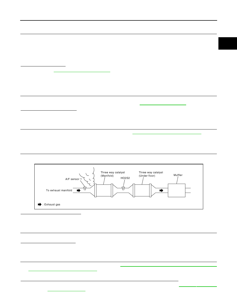
CHECK EXHAUST GAS LEAKAGE
1.
Start engine and run it at idle.
2.
Listen for an exhaust gas leakage before three way catalyst (manifold).
Is exhaust gas leakage detected?
YES
>> Repair or replace malfunctioning part.
NO
>> GO TO 4.
4.
CHECK FOR INTAKE AIR LEAKAGE
Listen for an intake air leakage after the mass air flow sensor.
Is intake air leakage detected?
YES
>> Repair or replace malfunctioning part.
NO
>> GO TO 5.
5.
CLEAR THE MIXTURE RATIO SELF-LEARNING VALUE
1.
Clear the mixture ratio self-learning value. Refer to
EC-585, "MIXTURE RATIO SELF-LEARNING VALUE
CLEAR : Special Repair Requirement"
.
2.
Run engine for at least 10 minutes at idle speed.
Is the 1st trip DTC P0171, P172, P0174 or P0175 detected? Is it difficult to start engine?
YES
>> Perform trouble diagnosis for DTC P0171, P0174 or P0172, P0175. Refer to
or
NO
>> GO TO 6.
PBIB1216E

EC-818
< DTC/CIRCUIT DIAGNOSIS >
[VK50VE]
P0133, P0153 A/F SENSOR 1
6.
CHECK A/F SENSOR 1 POWER SUPPLY CIRCUIT
1.
Disconnect A/F sensor 1 harness connector.
2.
Turn ignition switch ON.
3.
Check the voltage between A/F sensor 1 harness connector and ground.
Is the inspection result normal?
YES
>> GO TO 8.
NO
>> GO TO 7.
7.
DETECT MALFUNCTIONING PART
Check the following.
• Harness connectors E10, F10
• IPDM E/R harness connector E7
• 15 A fuse (No. 46)
• Harness for open or short between A/F sensor 1 and fuse
>> Repair or replace harness or connectors.
8.
CHECK A/F SENSOR 1 INPUT SIGNAL CIRCUIT FOR OPEN AND SHORT
1.
Turn ignition switch OFF.
2.
Disconnect ECM harness connector.
3.
Check the continuity between A/F sensor 1 harness connector and ECM harness connector.
4.
Check the continuity between A/F sensor 1 harness connector and ground, or ECM harness connector
and ground.
5.
Also check harness for short to power.
Is the inspection result normal?
YES
>> GO TO 9.
NO
>> Repair open circuit, short to ground or short to power in harness or connectors.
9.
CHECK A/F SENSOR 1 HEATER
EC-762, "Component Inspection"
Is the inspection result normal?
YES
>> GO TO 10.
DTC
A/F sensor 1
Ground
Voltage
Bank
Connector
Terminal
P0133
1
F67
4
Ground
Battery voltage
P0153
2
F68
4
DTC
A/F sensor 1
ECM
Continuity
Bank
Connector
Terminal
Connector
Terminal
P0133
1
F67
1
F111
81
Existed
2
82
P0153
2
F68
1
85
2
86
DTC
A/F sensor 1
ECM
Ground
Continuity
Bank
Connector
Terminal
Connector
Terminal
P0133
1
F67
1
F111
81
Ground
Not existed
2
82
P0153
2
F68
1
85
2
86

P0133, P0153 A/F SENSOR 1
EC-819
< DTC/CIRCUIT DIAGNOSIS >
[VK50VE]
C
D
E
F
G
H
I
J
K
L
M
A
EC
N
P
O
NO
>> GO TO 13.
10.
CHECK MASS AIR FLOW SENSOR
Check both mass air flow sensor (bank 1) and mass air flow sensor (bank 2).
Refer to
EC-748, "Component Inspection"
Is the inspection result normal?
YES
>> GO TO 11.
NO
>> Replace malfunctioning mass air flow sensor.
11.
CHECK PCV VALVE
EC-1125, "Component Inspection"
.
Is the inspection result normal?
YES
>> GO TO 12.
NO
>> Repair or replace PCV valve.
12.
CHECK INTERMITTENT INCIDENT
Perform
GI-36, "Intermittent Incident"
.
Is the inspection result normal?
YES
>> GO TO 13.
NO
>> Repair or replace malfunctioning part.
13.
REPLACE A/F SENSOR 1
Replace malfunctioning A/F sensor 1.
CAUTION:
• Discard any A/F sensor which has been dropped from a height of more than 0.5 m (19.7 in) onto a
hard surface such as a concrete floor; use a new one.
• Before installing new A/F sensor, clean exhaust system threads using Oxygen Sensor Thread
Cleaner [commercial service tool (J-43897-18 or J-43897-12)] and approved anti-seize lubricant
(commercial service tool).
>> INSPECTION END
EC-820
< DTC/CIRCUIT DIAGNOSIS >
[VK50VE]
P0137, P0157 HO2S2
P0137, P0157 HO2S2
Description
INFOID:0000000005237304
The heated oxygen sensor 2, after three way catalyst (manifold),
monitors the oxygen level in the exhaust gas on each bank.
Even if switching characteristics of the air fuel ratio (A/F) sensor 1
are shifted, the air fuel ratio is controlled to stoichiometric, by the sig-
nal from the heated oxygen sensor 2.
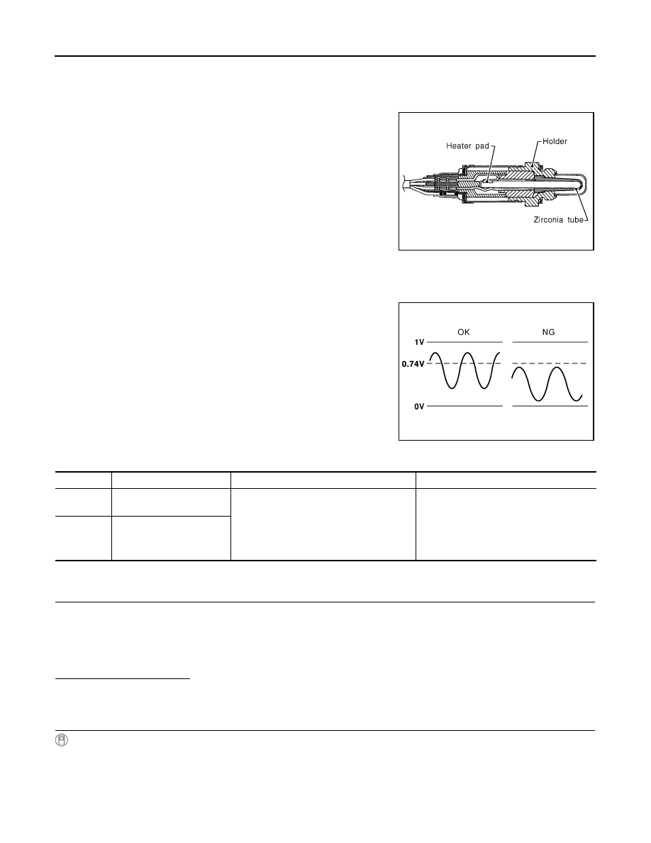
This sensor is made of ceramic zirconia. The zirconia generates volt-
age from approximately 1 V in richer conditions to 0 V in leaner con-
ditions.
Under normal conditions the heated oxygen sensor 2 is not used for
engine control operation.
DTC Logic
INFOID:0000000005237305
DTC DETECTION LOGIC
The heated oxygen sensor 2 has a much longer switching time
between rich and lean than the air fuel ratio (A/F) sensor 1. The oxy-
gen storage capacity of the three way catalyst (manifold) causes the
longer switching time. To judge the malfunctions of heated oxygen
sensor 2, ECM monitors whether the maximum voltage of the sensor
is sufficiently high during various driving conditions such as fuel cut.
DTC CONFIRMATION PROCEDURE
1.
PRECONDITIONING
If DTC Confirmation Procedure has been previously conducted, always perform the following procedure
before conducting the next test.
1.
Turn ignition switch OFF and wait at least 10 seconds.
2.
Turn ignition switch ON.
3.
Turn ignition switch OFF and wait at least 10 seconds.
Will CONSULT-III be used?
YES
>> GO TO 2.
NO
>> GO TO 4.
2.
PERFORM DTC CONFIRMATION PROCEDURE
With CONSULT-III
TESTING CONDITION:
For better results, perform “DTC WORK SUPPORT” at a temperature of 0 to 30
°
C (32 to 86
°
F).
1.
Start engine and warm it up to the normal operating temperature.
2.
Turn ignition switch OFF and wait at least 10 seconds.
3.
Turn ignition switch ON.
SEF327R
JMBIA1572GB
DTC No.
Trouble diagnosis name
DTC detecting condition
Possible cause
P0137
Heated oxygen sensor 2
(bank 1) circuit low voltage
The maximum voltage from the sensor does
not reach the specified voltage.
• Harness or connectors
(The sensor circuit is open or shorted)
• Heated oxygen sensor 2
• Fuel pressure
• Fuel injector
• Intake air leaks
P0157
Heated oxygen sensor 2
(bank 2) circuit low voltage
Нет комментариевНе стесняйтесь поделиться с нами вашим ценным мнением.
Текст