Infiniti FX35, FX50 (S51). Manual — part 820

P0137, P0157 HO2S2
EC-821
< DTC/CIRCUIT DIAGNOSIS >
[VK50VE]
C
D
E
F
G
H
I
J
K
L
M
A
EC
N
P
O
4.
Turn ignition switch OFF and wait at least 10 seconds.
5.
Restart engine and keep the engine speed between 3,500 and 4,000 rpm for at least 1 minute under no
load.
6.
Let engine idle for 1 minute.
7.
Select “DATA MONITOR” mode with CONSULT-III.
8.
Check that “COOLAN TEMP/S” indicates more than 70
°
C (158
°
F).
If not, warm up engine and go to next step when “COOLAN TEMP/S” indication reaches 70
°
C (158
°
F).
9.
Open engine hood.
10. Select “HO2S2 (B1) P1147” (for DTC P0137) or “HO2S2 (B2) P1167” (for DTC P0157) of “HO2S2” in
“DTC WORK SUPPORT” mode with CONSULT-III.
11. Follow the instruction of CONSULT-III display.
NOTE:
It will take at most 10 minutes until “COMPLETED” is displayed.
12. Touch “SELF-DIAG RESULTS”.
Which is displayed on CONSULT-III screen?
OK
>> INSPECTION END
NG
>> Go to
CAN NOT BE DIAGNOSED>>GO TO 3.
3.
PERFORM DTC CONFIRMATION PROCEDURE AGAIN
1.
Turn ignition switch OFF and leave the vehicle in a cool place (soak the vehicle).
2.
Perform DTC confirmation procedure again.
>> GO TO 2.
4.
PERFORM COMPONENT FUNCTION CHECK
With GST
Perform component function check. Refer to
EC-821, "Component Function Check"
.
NOTE:
Use component function check to check the overall function of the heated oxygen sensor 2 circuit. During this
check, a 1st trip DTC might not be confirmed.
Is the inspection result normal?
YES
>> INSPECTION END
NO
>> Go to
Component Function Check
INFOID:0000000005237306
1.
PERFORM COMPONENT FUNCTION CHECK-I
With GST
1.
Start engine and warm it up to the normal operating temperature.
2.
Turn ignition switch OFF and wait at least 10 seconds.
3.
Turn ignition switch ON.
4.
Turn ignition switch OFF and wait at least 10 seconds.
5.
Restart engine and keep the engine speed between 3,500 and 4,000 rpm for at least 1 minute under no
load.
6.
Let engine idle for 1 minute.
7.
Check the voltage between ECM harness connector terminals under the following conditions.
Is the inspection result normal?
YES
>> INSPECTION END
NO
>> GO TO 2.
DTC
ECM
Condition
Voltage
Connector
+
–
Terminal
Terminal
P0137
F110
32
31
Revving up to 4,000 rpm under no load at
least 10 times
The voltage should be above 0.74 V at
least once during this procedure.
P0157
36

EC-822
< DTC/CIRCUIT DIAGNOSIS >
[VK50VE]
P0137, P0157 HO2S2
2.
PERFORM COMPONENT FUNCTION CHECK-II
Check the voltage between ECM harness connector terminals under the following conditions.
Is the inspection result normal?
YES
>> INSPECTION END
NO
>> GO TO 3.
3.
PERFORM COMPONENT FUNCTION CHECK-III
Check the voltage between ECM harness connector terminals under the following conditions.
Is the inspection result normal?
YES
>> INSPECTION END
NO
>> Go to
Diagnosis Procedure
INFOID:0000000005237307
1.
CHECK GROUND CONNECTION
1.
Turn ignition switch OFF.
2.
Check ground connection M95. Refer to Ground Inspection in
Is the inspection result normal?
YES
>> GO TO 2.
NO
>> Repair or replace ground connection.
2.
CLEAR THE MIXTURE RATIO SELF-LEARNING VALUE
1.
Clear the mixture ratio self-learning value. Refer to
EC-585, "MIXTURE RATIO SELF-LEARNING VALUE
CLEAR : Special Repair Requirement"
.
2.
Run engine for at least 10 minutes at idle speed.
Is the 1st trip DTC P0171 or P0174 detected? Is it difficult to start engine?
YES
>> Perform trouble diagnosis for DTC P0171 or P0174. Refer to
NO
>> GO TO 3.
3.
CHECK HEATED OXYGEN SENSOR 2 GROUND CIRCUIT FOR OPEN AND SHORT
1.
Turn ignition switch OFF.
2.
Disconnect heated oxygen sensor 2 (HO2S2) harness connector.
3.
Disconnect ECM harness connector.
4.
Check the continuity between HO2S2 harness connector and ECM harness connector.
5.
Also check harness for short to ground and short to power.
DTC
ECM
Condition
Voltage
Connector
+
–
Terminal
Terminal
P0137
F110
32
31
Keeping engine at idle for 10 minutes
The voltage should be above 0.74 V at
least once during this procedure.
P0157
36
DTC
ECM
Condition
Voltage
Connector
+
–
Terminal
Terminal
P0137
F110
32
31
Coasting from 80 km/h (50 MPH) with se-
lector lever in the D position
The voltage should be above 0.74 V at
least once during this procedure.
P0157
36
DTC
HO2S2
ECM
Continuity
Bank
Connector
Terminal
Connector
Terminal
P0137
1
F87
1
F110
31
Existed
P0157
2
F88
1

P0137, P0157 HO2S2
EC-823
< DTC/CIRCUIT DIAGNOSIS >
[VK50VE]
C
D
E
F
G
H
I
J
K
L
M
A
EC
N
P
O
Is the inspection result normal?
YES
>> GO TO 4.
NO
>> Repair open circuit, short to ground or short to power in harness or connectors.
4.
CHECK HO2S2 INPUT SIGNAL CIRCUIT FOR OPEN AND SHORT
1.
Check the continuity between HO2S2 harness connector and ECM harness connector.
2.
Check the continuity between HO2S2 harness connector and ground, or ECM harness connector and
ground.
3.
Also check harness for short to power.
Is the inspection result normal?
YES
>> GO TO 5.
NO
>> Repair open circuit, short to ground or short to power in harness or connectors.
5.
CHECK HEATED OXYGEN SENSOR 2
EC-823, "Component Inspection"
Is the inspection result normal?
YES
>> GO TO 7.
NO
>> GO TO 6.
6.
REPLACE HEATED OXYGEN SENSOR 2
Replace malfunctioning heated oxygen sensor 2.
CAUTION:
• Discard any heated oxygen sensor which has been dropped from a height of more than 0.5 m (19.7
in) onto a hard surface such as a concrete floor; use a new one.
• Before installing new oxygen sensor, clean exhaust system threads using Oxygen Sensor Thread
Cleaner [commercial service tool (J-43897-18 or J-43897-12)] and approved anti-seize lubricant
(commercial service tool).
>> INSPECTION END
7.
CHECK INTERMITTENT INCIDENT
GI-36, "Intermittent Incident"
.
>> INSPECTION END
Component Inspection
INFOID:0000000005237308
1.
INSPECTION START
Will CONSULT-III be used?
Will CONSULT-III be used?
YES
>> GO TO 2.
NO
>> GO TO 3.
2.
CHECK HEATED OXYGEN SENSOR 2
DTC
HO2S2
ECM
Continuity
Bank
Connector
Terminal
Connector
Terminal
P0137
1
F87
4
F110
32
Existed
P0157
2
F88
4
36
DTC
HO2S2
ECM
Ground
Continuity
Bank
Connector
Terminal
Connector
Terminal
P0137
1
F87
4
F110
32
Ground
Not existed
P0157
2
F88
4
36
EC-824
< DTC/CIRCUIT DIAGNOSIS >
[VK50VE]
P0137, P0157 HO2S2
With CONSULT-III
1.
Start engine and warm it up to the normal operating temperature.
2.
Start engine and keep the engine speed between 3,500 and 4,000 rpm for at least 1 minute under no load.
3.
Let engine idle for 1 minute.
4.
Select “FUEL INJECTION” in “ACTIVE TEST” mode, and select “HO2S2 (B1)/(B2)” as the monitor item
with CONSULT-III.
5.
Check “HO2S2 (B1)/(B2)” at idle speed when adjusting “FUEL INJECTION” to
±
25%.
“HO2S2 (B1)/(B2)” should be above 0.74 V at least once when the “FUEL INJECTION” is +25%.
“HO2S2 (B1)/(B2)” should be below 0.18 V at least once when the “FUEL INJECTION” is
−
25%.
Is the inspection result normal?
YES
>> INSPECTION END
NO
>> GO TO 6.
3.
CHECK HEATED OXYGEN SENSOR 2-I
Without CONSULT-III
1.
Start engine and warm it up to the normal operating temperature.
2.
Turn ignition switch OFF and wait at least 10 seconds.
3.
Start engine and keep the engine speed between 3,500 and 4,000 rpm for at least 1 minute under no load.
4.
Let engine idle for 1 minute.
5.
Check the voltage between ECM harness connector terminals under the following conditions.
Is the inspection result normal?
YES
>> INSPECTION END
NO
>> GO TO 4.
4.
CHECK HEATED OXYGEN SENSOR 2-II
Check the voltage between ECM harness connector terminals under the following conditions.
JMBIA1573GB
ECM
Condition
Voltage
Connector
+
–
Terminal
Terminal
F110
32
[HO2S2
(bank 1)]
31
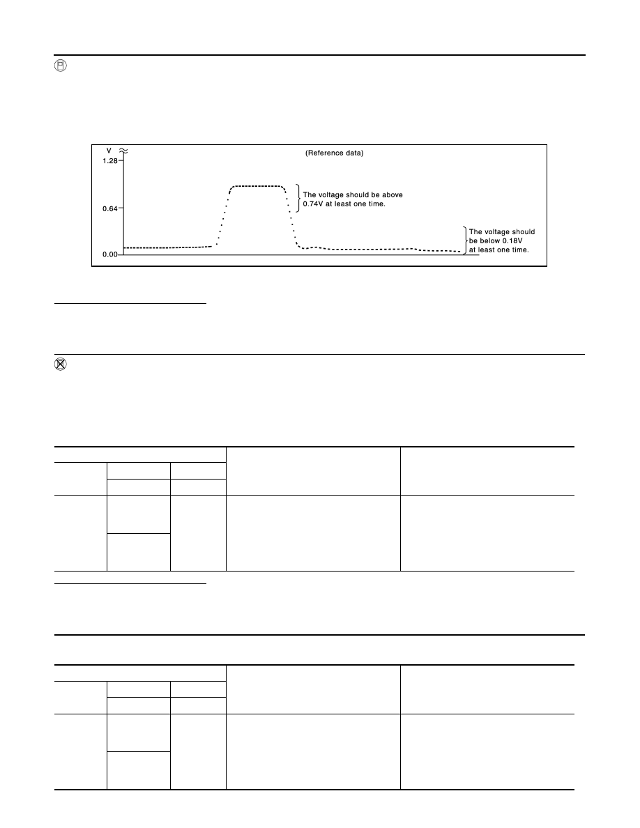
Revving up to 4,000 rpm under no load at
least 10 times
The voltage should be above 0.74 V at
least once during this procedure.
The voltage should be below 0.18 V at
least once during this procedure.
36
[HO2S2
(bank 2)]
ECM
Condition
Voltage
Connector
+
–
Terminal
Terminal
F110
32
[HO2S2
(bank 1)]
31
Keeping engine at idle for 10 minutes
The voltage should be above 0.74 V at
least once during this procedure.
The voltage should be below 0.18 V at
least once during this procedure.
36
[HO2S2
(bank 2)]
Нет комментариевНе стесняйтесь поделиться с нами вашим ценным мнением.
Текст