Infiniti FX35, FX50 (S51). Manual — part 948
EM-92
< UNIT DISASSEMBLY AND ASSEMBLY >
[VQ35HR]
ENGINE STAND SETTING
UNIT DISASSEMBLY AND ASSEMBLY
ENGINE STAND SETTING
Setting
INFOID:0000000005245161
NOTE:
Explained here is how to disassemble with engine stand supporting transmission surface. When using differ-
ent type of engine stand, note with difference in steps and etc.
1.
Remove the engine assembly from the vehicle. Refer to
(2WD models) or
(AWD models).
2.
Remove crankshaft pulley. Refer to
NOTE:
The drive plate is fixed with a ring gear stopper [SST: KV10118600 (J-48641)]. Loosen the crankshaft pul-
ley mounting bolts before installing the engine stand.
3.
Remove the parts that may restrict installation of engine to a widely use engine stand.
• Fix crankshaft with a ring gear stopper [SST: KV10118600 (J-48641)]. Loosen drive plate mounting bolt
with power tool.
• Check for deformation or damage of drive plate. Refer to
.
NOTE:
The procedure is described assuming that you use a widely use engine stand holding the surface, to
which transmission is installed.
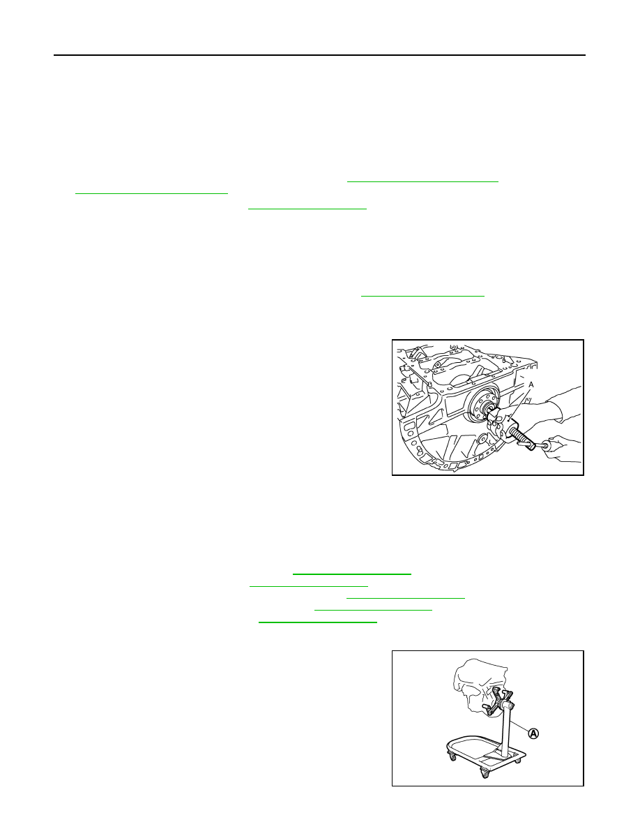
4.
Remove pilot converter using the pilot bushing puller [SST:
ST16610001 (J-23907)] (A), if necessary.
5.
Lift the engine with hoist to install it onto the widely use engine stand.
CAUTION:
Use an engine stand that has a load capacity [220 kg (485 lb) or more] large enough for supporting
the engine weight.
• If the load capacity of the stand is not adequate, remove the following parts beforehand to reduce the
potential risk of overturning the stand.
- Remove intake manifold collector. Refer to
- Remove intake manifold. Refer to
- Remove fuel injector and fuel tube assembly. Refer to
.
- Remove ignition coil and rocker cover. Refer to
.
- Remove exhaust manifold. Refer to
- Other removable brackets.
NOTE:
The figure shows an example of widely use engine stand (A)
that can hold mating surface of transmission with drive plate
removed.
CAUTION:
Before removing the hanging chains, check the engine
stand is stable and there is no risk of overturning.
JPBIA0193ZZ
JPBIA0190ZZ
ENGINE STAND SETTING
EM-93
< UNIT DISASSEMBLY AND ASSEMBLY >
[VQ35HR]
C
D
E
F
G
H
I
J
K
L
M
A
EM
N
P
O
6.
Drain engine oil. Refer to
.
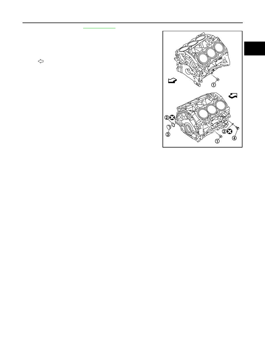
7.
Drain engine coolant by removing water drain plugs (1) and (4)
from cylinder block both sides as shown in the figure.
2
: Washer
3
: Plug
: Engine front
JPBIA0191ZZ

EM-94
< UNIT DISASSEMBLY AND ASSEMBLY >
[VQ35HR]
ENGINE UNIT
ENGINE UNIT
Disassembly
INFOID:0000000005245162
1.
Remove intake manifold collector. Refer to
2.
Remove intake manifold. Refer to
3.
Remove exhaust manifold. Refer to
.
4.
Remove oil pan (lower). Refer to
5.
Remove ignition coil, spark plug and rocker cover. Refer to
6.
Remove fuel injector and fuel tube. Refer to
7.
Remove timing chain. Refer to
.
8.
Remove rear timing chain case. Refer to
.
9.
Remove camshaft. Refer to
10. Remove cylinder head. Refer to
Assembly
INFOID:0000000005245163
Assembly in the reverse order of disassembly.
REAR TIMING CHAIN CASE
EM-95
< UNIT DISASSEMBLY AND ASSEMBLY >
[VQ35HR]
C
D
E
F
G
H
I
J
K
L
M
A
EM
N
P
O
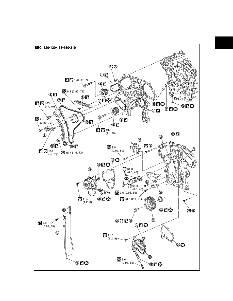
REAR TIMING CHAIN CASE
Exploded View
INFOID:0000000005245164
1.
Timing chain (secondary)
2.
Camshaft sprocket (EXH)
3.
O-ring
4.
Timing chain (secondary)
5.
Camshaft sprocket (EXH)
6.
Internal chain guide
7.
Timing chain (primary)
8.
Camshaft sprocket (INT)
9.
Timing chain tensioner (primary)
JPBIA2441GB
Нет комментариевНе стесняйтесь поделиться с нами вашим ценным мнением.
Текст