Infiniti FX35, FX50 (S51). Manual — part 946
EM-84
< UNIT REMOVAL AND INSTALLATION >
[VQ35HR]
ENGINE ASSEMBLY
• Install plug to avoid leakage of A/T fluid and power steering fluid.
2.
Disconnect heated oxygen sensor 2 harness.
3.
Remove three way catalyst and exhaust front tube. Refer to
.
4.
Disconnect steering lower joint at power steering gear assembly side, and release steering lower shaft.
Refer to
ST-18, "WITHOUT ELECTRIC MOTOR : Exploded View"
or
.
5.
Remove rear propeller shaft. Refer to
.
6.
Disengage A/T control rod at A/T shift selector side. Then, temporarily secure it on the transmission
assembly, so that it does not sag. Refer to
7.
Preparation for the separation work of transaxle is as per the following:
• Remove rear plate cover from oil pan (upper). Then remove bolts fixing drive plate to torque converter.
Refer to
.
• Remove transmission joint bolts that pierce at oil pan (upper) lower rear side. Refer to
.
8.
Remove front stabilizer connecting rod from transverse link. Refer to
.
9.
Remove lower ends of left and right steering knuckle from transverse link. Refer to
.
10. Separate steering outer sockets from steering knuckle. Refer to
.
11. Remove transverse links mounting bolts at suspension member side. Refer to
Removal Work
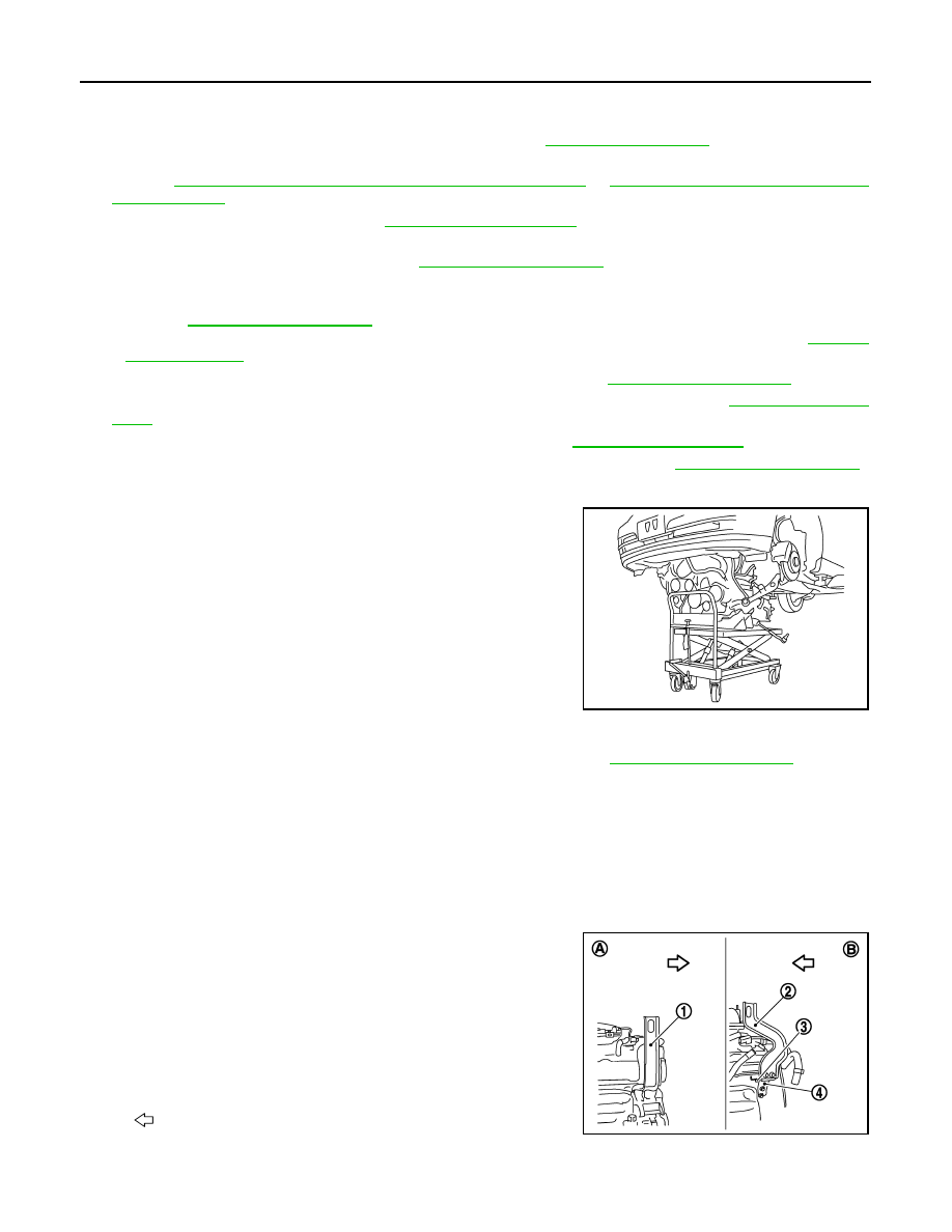
1.
Use a manual lift table caddy (commercial service tool) or an
equivalently rigid tool such as a transmission jack. Securely sup-
port bottom of suspension member and the transmission assem-
bly.
CAUTION:
Put a piece of wood or something similar as the supporting
surface, secure a completely stable condition.
2.
Remove rear engine mounting member bolts.
3.
Remove front suspension member mounting bolts and nuts. Refer to
.
4.
Carefully lower jack, or raise lift to remove the engine, the transmission assembly and front suspension
member. When performing work, observe the following caution:
CAUTION:
• Confirm there is no interference with the vehicle.
• Check that all connection points have been disconnected.
• Keep in mind the center of vehicle gravity changes. If necessary, use jack(s) to support the vehi-
cle at rear jacking point(s) to prevent it from falling it off the lift.
Separation Work
1.
Install engine slingers into front of cylinder head (bank 1) and
rear of cylinder head (bank 2).
PBIC0804E
1
: Engine front slinger
2
: Engine rear upper slinger
3
: Spacer
4
: Engine rear lower slinger
A
: Bank 1
B
: Bank 2
: Engine front
JPBIA0157ZZ
ENGINE ASSEMBLY
EM-85
< UNIT REMOVAL AND INSTALLATION >
[VQ35HR]
C
D
E
F
G
H
I
J
K
L
M
A
EM
N
P
O
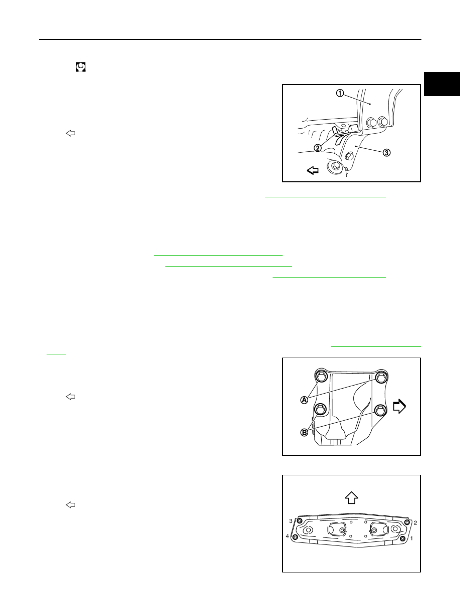
• To protect rocker cover against damage caused by tilting of
engine slinger, insert spacer between cylinder head and
engine rear lower slinger (3), in direction shown in the figure.
NOTE:
Spacer (2) is a component part of engine rear upper slinger
assembly.
2.
Remove power steering oil pump from engine side. Refer to
ST-36, "VQ35HR : Exploded View"
.
3.
Remove engine mounting insulators (RH and LH) under side nuts with power tool.
4.
Lift with hoist and separate the engine and the transmission assembly from front suspension member.
CAUTION:
• Before and during this lifting, always check that any harnesses are left connected.
• Never damage to and oil/grease smearing or spills onto engine mounting insulator.
5.
Remove alternator. Refer to
CHG-29, "VQ35HR : Exploded View"
.
6.
Remove starter motor. Refer to
STR-18, "VQ35HR : Exploded View"
.
7.
Separate the engine from the transmission assembly. Refer to
8.
Remove each engine mounting insulator and each engine mounting bracket from the engine with power
tool.
INSTALLATION
Note the following item, and install in the reverse order of removal.
• Do not allow engine mounting insulator to be damage and careful no oil gets on it.
• For a location with a positioning pin, insert it securely into hole of mating part.
• For a part with a specified installation orientation, refer to component figure in
.
• When installing engine mounting bracket (RH and LH) on cylinder
block, tighten two upper bolts [shown as (A) in the figure] first.
Then tighten two lower bolts [shown as (B) in the figure].
• Check all engine mounting insulators are seated properly, then tighten mounting nuts.
• Tighten rear engine mounting member bolts in numerical order as
shown in the figure.
Slinger bolts:
: 28.0 N·m (2.9 kg-m, 21 ft-lb)
1
: Engine rear upper slinger
: Engine front
JPBIA0158ZZ
: Engine front
JPBIA2097ZZ
: Vehicle front
JPBIA0160ZZ

EM-86
< UNIT REMOVAL AND INSTALLATION >
[VQ35HR]
ENGINE ASSEMBLY
2WD : Inspection
INFOID:0000000005245157
INSPECTION AFTER INSTALLATION
Inspection for Leakage
The following are procedures for checking fluids leakage, lubricates leakage and exhaust gases leakage.
• Before starting engine, check oil/fluid levels including engine coolant and engine oil. If less than required
quantity, fill to the specified level. Refer to
MA-12, "Fluids and Lubricants"
.
• Use procedure below to check for fuel leakage.
- Turn ignition switch “ON” (with engine stopped). With fuel pressure applied to fuel piping, check for fuel leak-
age at connection points.
- Start engine. With engine speed increased, check again for fuel leakage at connection points.
• Run engine to check for unusual noise and vibration.
• Warm up engine thoroughly to check there is no leakage of fuel, exhaust gases, or any oil/fluids including
engine oil and engine coolant.
• Bleed air from lines and hoses of applicable lines, such as in cooling system.
• After cooling down engine, again check oil/fluid levels including engine oil and engine coolant. Refill to the
specified level, if necessary.
Summary of the inspection items:
*: Transmission/transaxle/CVT fluid, power steering fluid, brake fluid, etc.
AWD
Items
Before starting engine
Engine running
After engine stopped
Engine coolant
Level
Leakage
Level
Engine oil
Level
Leakage
Level
Other oils and fluid*
Level
Leakage
Level
Fuel
Leakage
Leakage
Leakage
Exhaust gases
—
Leakage
—
ENGINE ASSEMBLY
EM-87
< UNIT REMOVAL AND INSTALLATION >
[VQ35HR]
C
D
E
F
G
H
I
J
K
L
M
A
EM
N
P
O
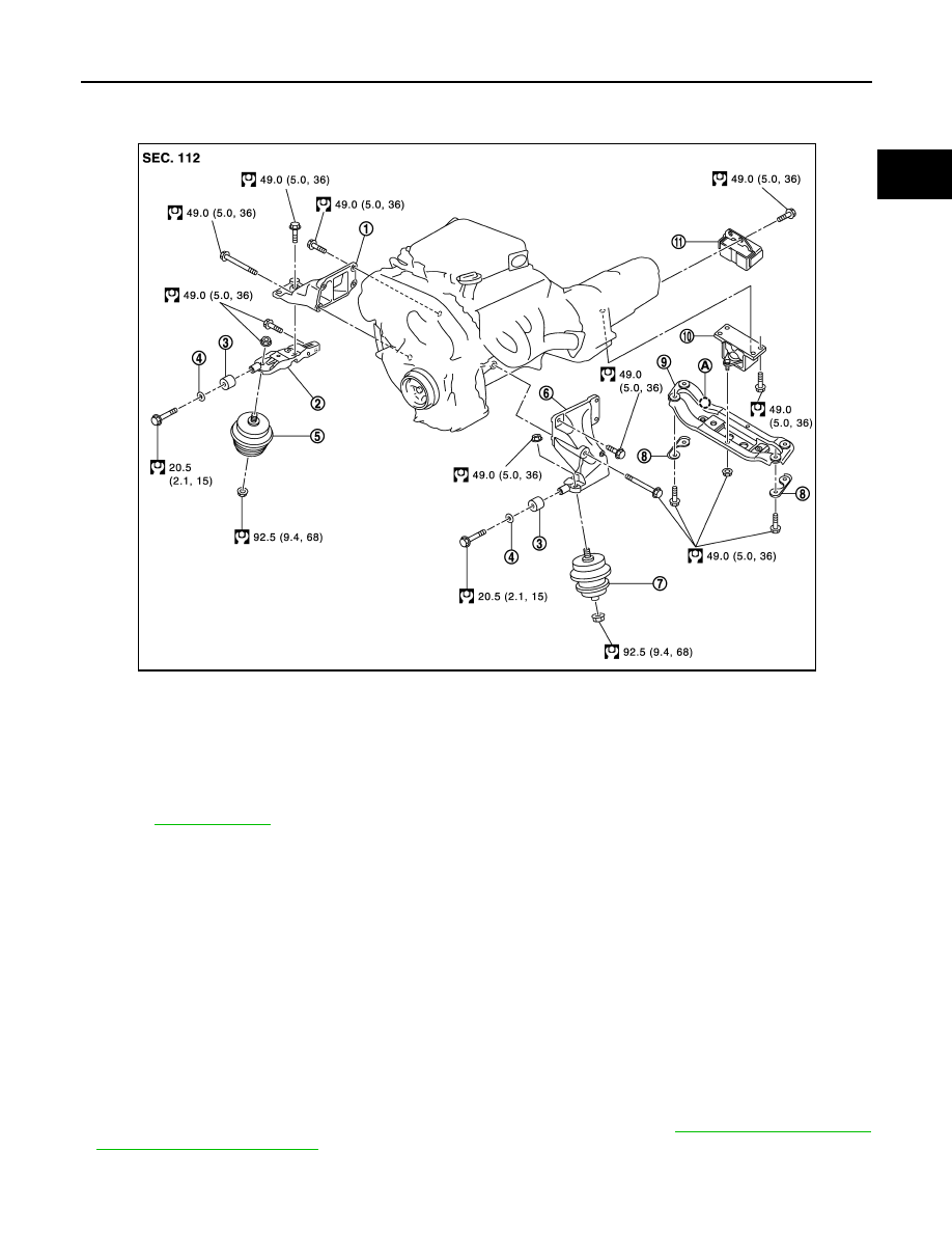
AWD : Exploded View
INFOID:0000000005245158
AWD : Removal and Installation
INFOID:0000000005245159
WARNING:
• Situate the vehicle on a flat and solid surface.
• Place chocks at front and back of rear wheels.
• For engines not equipped with engine slingers, attach proper slingers and bolts described in PARTS
CATALOG.
CAUTION:
• Always be careful to work safely, avoid forceful or uninstructed operations.
• Never start working until exhaust system and engine coolant are cool enough.
• If items or work required are not covered by the engine section, refer to the applicable sections.
• Always use the support point specified for lifting.
• Use either 2-pole lift type or separate type lift as best you can. If board-on type is used for unavoid-
able reasons, support at rear axle jacking point with transmission jack or similar tool before starting
work, in preparation for the backward shift of center of gravity.
• For supporting points for lifting and jacking point at rear axle, refer to
REMOVAL
1.
Engine mounting bracket (RH)
2.
Engine mounting bracket (RH) (low-
er)
3.
Dynamic damper
4.
Washer
5.
Engine mounting insulator (RH)
6.
Engine mounting bracket (LH)
7.
Engine mounting insulator (LH)
8.
Heat insulator
9.
Rear engine mounting member
10.
Engine mounting insulator (rear)
11.
Dynamic damper
A.
Front mark
Refer to
for symbols in the figure.
JPBIA2100GB
Нет комментариевНе стесняйтесь поделиться с нами вашим ценным мнением.
Текст