Infiniti FX35, FX50 (S51). Manual — part 947

EM-88
< UNIT REMOVAL AND INSTALLATION >
[VQ35HR]
ENGINE ASSEMBLY
Outline
At first, remove the engine, the transmission assembly, the transfer assembly and the front final drive assem-
bly with front suspension member downward. Then separate the engine, the transmission assembly, the trans-
fer and the front final drive assembly.
Preparation
1.
Release fuel pressure. Refer to
.
2.
Disconnect both battery terminals. Refer to
3.
Drain engine coolant from radiator. Refer to
.
CAUTION:
• Perform this step when engine is cold.
• Never spill engine coolant on drive belt.
4.
Remove the following parts:
• Radiator reservoir tank: Refer to
• Engine cover: Refer to
• Front road wheel and tires (power tool)
• Engine undercover (power tool)
• Front cross bar: Refer to
• Cowl top cover: Refer to
.
• Air duct and air cleaner case assembly: Refer to
.
5.
Discharge refrigerant from A/C circuit. Refer to
HA-25, "Collection and Charge"
6.
Remove radiator hoses (upper and lower). Refer to
.
Engine Room LH
1.
Disconnect heater hose from vehicle-side, and fit a plug onto hose end to prevent engine coolant leakage.
2.
Disconnect A/C piping from A/C compressor, and temporarily fasten it on vehicle with a rope. Refer to
3.
Disconnect brake booster vacuum hose.
4.
Disconnect ground cables.
Engine Room RH
1.
Disconnect battery positive cable vehicle side and temporarily fasten it on engine.
2.
Disconnect all clips and connectors of the engine room harness from engine back side.
3.
Disconnect fuel feed hose (with damper) and EVAP hose. Refer to
CAUTION:
Fit plugs onto disconnected hoses to prevent fuel leakage.
4.
Remove reservoir tank of power steering oil pump and piping from vehicle, and temporarily secure them
on engine. Refer to
ST-48, "VQ35HR : Exploded View"
.
CAUTION:
When temporarily securing, keep the reservoir tank upright to avoid a fluid leakage.
Vehicle Inside
Follow procedure below to disconnect engine room harness connectors at passenger room side, and tempo-
rarily secure them on engine.
1.
Remove passenger-side kicking plate and dash side finisher. Refer to
.
2.
Disconnect engine room harness connectors at unit sides and other.
3.
Disengage intermediate fixing point. Pull out engine room harnesses to engine room side, and temporarily
secure them on engine.
CAUTION:
• When pulling out harnesses, take care not to damage harnesses and connectors.
• After temporarily securing, cover connectors with vinyl or similar material to protect against for-
eign material adhesion.
Vehicle Underbody
1.
Remove A/T fluid cooler hoses and power steering oil pump oil cooler hoses.
• Install plug to avoid leakage of A/T fluid and power steering fluid.
2.
Disconnect heated oxygen sensor 2 harness. Refer to
.
3.
Remove three way catalyst and exhaust front tube. Refer to
.
ENGINE ASSEMBLY
EM-89
< UNIT REMOVAL AND INSTALLATION >
[VQ35HR]
C
D
E
F
G
H
I
J
K
L
M
A
EM
N
P
O
4.
Disconnect steering lower joint at power steering gear assembly side, and release steering lower shaft.
Refer to
ST-18, "WITHOUT ELECTRIC MOTOR : Exploded View"
or
.
5.
Remove rear propeller shaft. Refer to
.
6.
Remove front drive shaft (both side). Refer to
7.
Disengage A/T control rod at A/T shift selector side. Then, temporarily secure it on the transmission
assembly, so that it does not sag. Refer to
8.
Preparation for the separation work of transaxle is as per the following:
• Remove rear plate cover from oil pan (upper). Then remove bolts fixing drive plate to torque converter.
Refer to
• Remove transmission joint bolts that pierce at oil pan (upper) lower rear side. Refer to
.
9.
Remove front stabilizer connecting rod from transverse link. Refer to
.
10. Remove lower ends of left and right steering knuckle from transverse link. Refer to
.
11. Separate steering outer sockets from steering knuckle. Refer to
.
12. Remove transverse links mounting bolts at suspension member side. Refer to
Removal Work
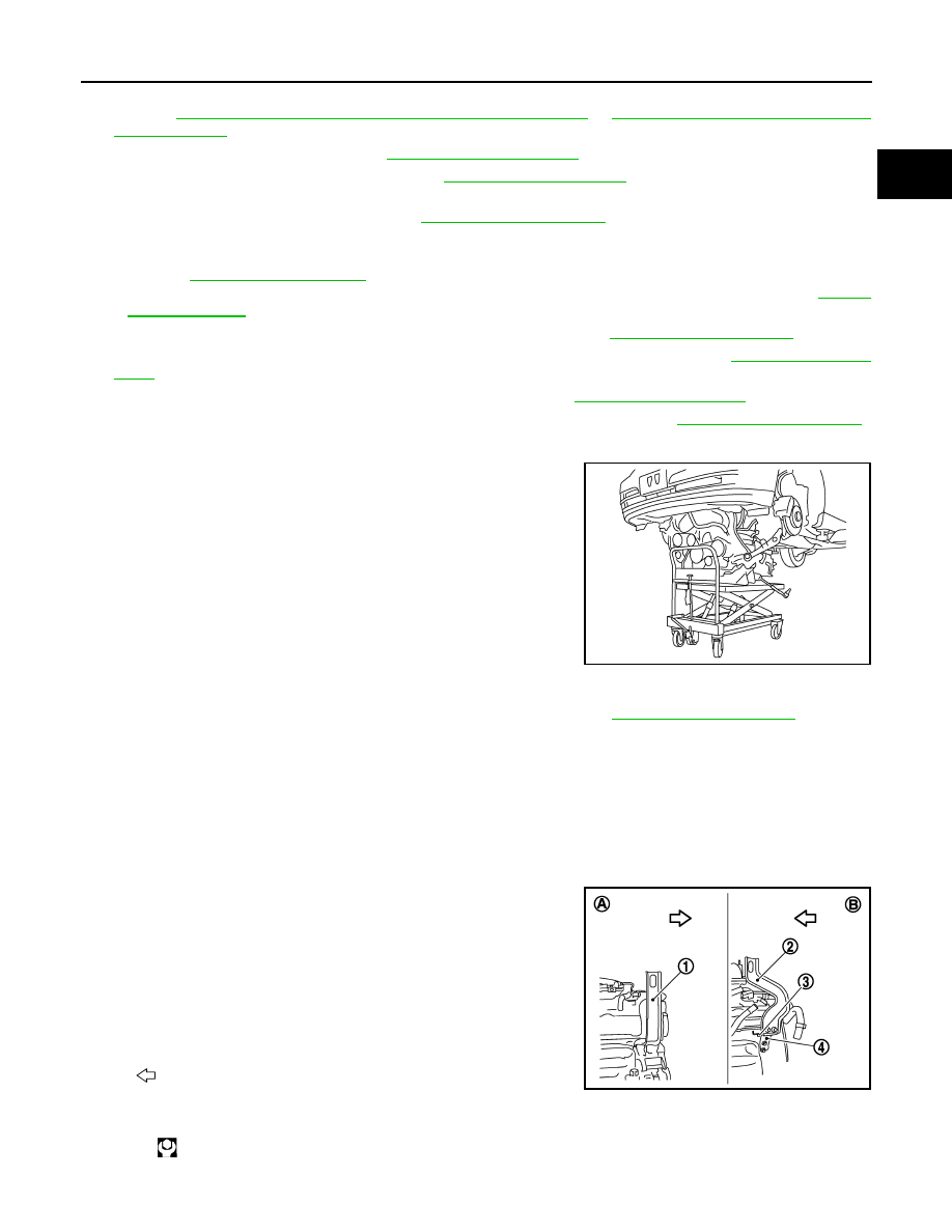
1.
Use a manual lift table caddy (commercial service tool) or an
equivalently rigid tool such as a transmission jack. Securely sup-
port bottom of suspension member and transmission.
CAUTION:
Put a piece of wood or something similar as the supporting
surface, secure a completely stable condition.
2.
Remove rear engine mounting member bolts.
3.
Remove front suspension member mounting bolts and nuts. Refer to
4.
Carefully lower jack, or raise lift to remove the engine, transmission, transfer and front final drive assembly
and front suspension member. When performing work, observe the following caution:
CAUTION:
• Confirm there is no interference with the vehicle.
• Check that all connection points have been disconnected.
• Keep in mind the center of the vehicle gravity changes. If necessary, use jack(s) to support the
vehicle at rear jacking point(s) to prevent it from falling it off the lift.
Separation Work
1.
Install engine slingers into front of cylinder head (bank 1) and
rear of cylinder head (bank 2).
PBIC0804E
1
: Engine front slinger
2
: Engine rear upper slinger
3
: Spacer
4
: Engine rear lower slinger
A
: Bank 1
B
: Bank 2
: Engine front
Slinger bolts:
: 28.0 N·m (2.9 kg-m, 21 ft-lb)
JPBIA0157ZZ
EM-90
< UNIT REMOVAL AND INSTALLATION >
[VQ35HR]
ENGINE ASSEMBLY
• To protect rocker cover against damage caused by tilting of
engine slinger, insert spacer between cylinder head and
engine rear lower slinger (3), in direction shown in the figure.
NOTE:
Spacer (2) is a component part of engine rear upper slinger
assembly.
2.
Remove power steering oil pump from engine side. Refer to
ST-36, "VQ35HR : Exploded View"
.
3.
Remove engine mounting insulators (RH and LH) under side nuts with power tool.
4.
Lift with hoist and separate the engine, the transmission assembly, the transfer assembly and the front
final drive assembly from front suspension member.
CAUTION:
• Before and during this lifting, always check if any harnesses are left connected.
• Never damage to and oil/grease smearing or spills onto engine mounting insulator.
5.
Remove alternator. Refer to
CHG-29, "VQ35HR : Exploded View"
.
6.
Remove starter motor. Refer to
STR-18, "VQ35HR : Exploded View"
.
7.
Remove front propeller shaft from the front final drive assembly side. Refer to
.
8.
Separate the engine from the transmission assembly. Refer to
9.
Remove the front final drive assembly from oil pan (upper). Refer to
.
10. Remove each engine mounting insulator and each engine mounting bracket from the engine with power
tool.
INSTALLATION
Note the following item, and install in the reverse order of removal.
• Do not allow engine mounting insulator to be damage and careful no engine oil gets on it.
• For a location with a positioning pin, insert it securely into hole of mating part.
• For a part with a specified installation orientation, refer to component figure in
.
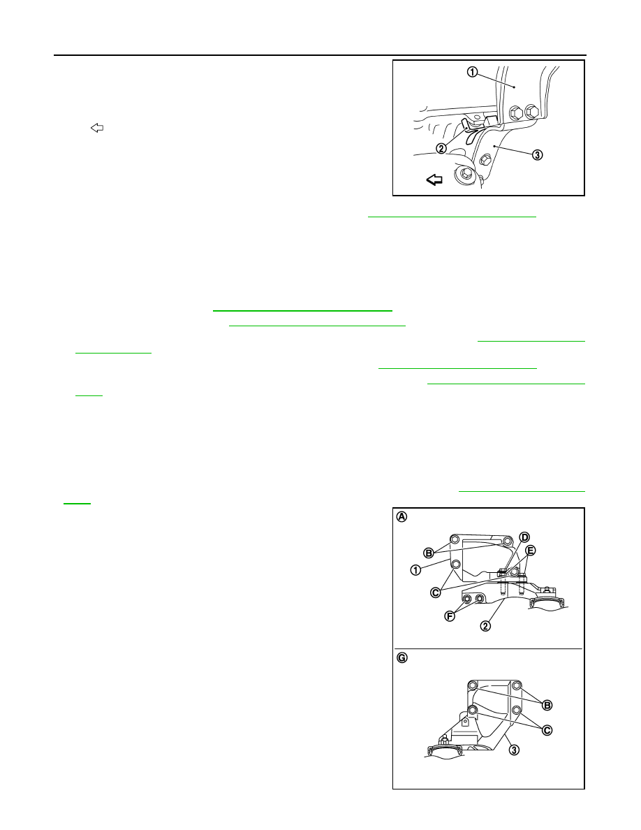
• When installing engine mounting bracket (RH and LH) on cylinder
block, tighten two upper bolts (B) first. Then tighten two lower bolts
(C).
• Install engine mounting bracket (RH) (lower) (2) as per the follow-
ing:
- Temporarily tighten mounting bolts [shown as (D), (E) and (F) in
the figure].
- Tighten mounting bolts to the specified torque with following
mounting surfaces touched.
• Engine mounting bracket (RH) (1) to engine mounting bracket
(RH) (lower) [shown as and in figure].
• Front final drive to engine mounting bracket (RH) (lower) [shown
as in figure].
• Check all engine mounting insulators are seated properly, then
tighten mounting nuts.
1
: Engine rear upper slinger
: Engine front
JPBIA0158ZZ
3
: Engine mounting bracket (LH)
A
: Right side
G : Left side
JPBIA2466ZZ
ENGINE ASSEMBLY
EM-91
< UNIT REMOVAL AND INSTALLATION >
[VQ35HR]
C
D
E
F
G
H
I
J
K
L
M
A
EM
N
P
O
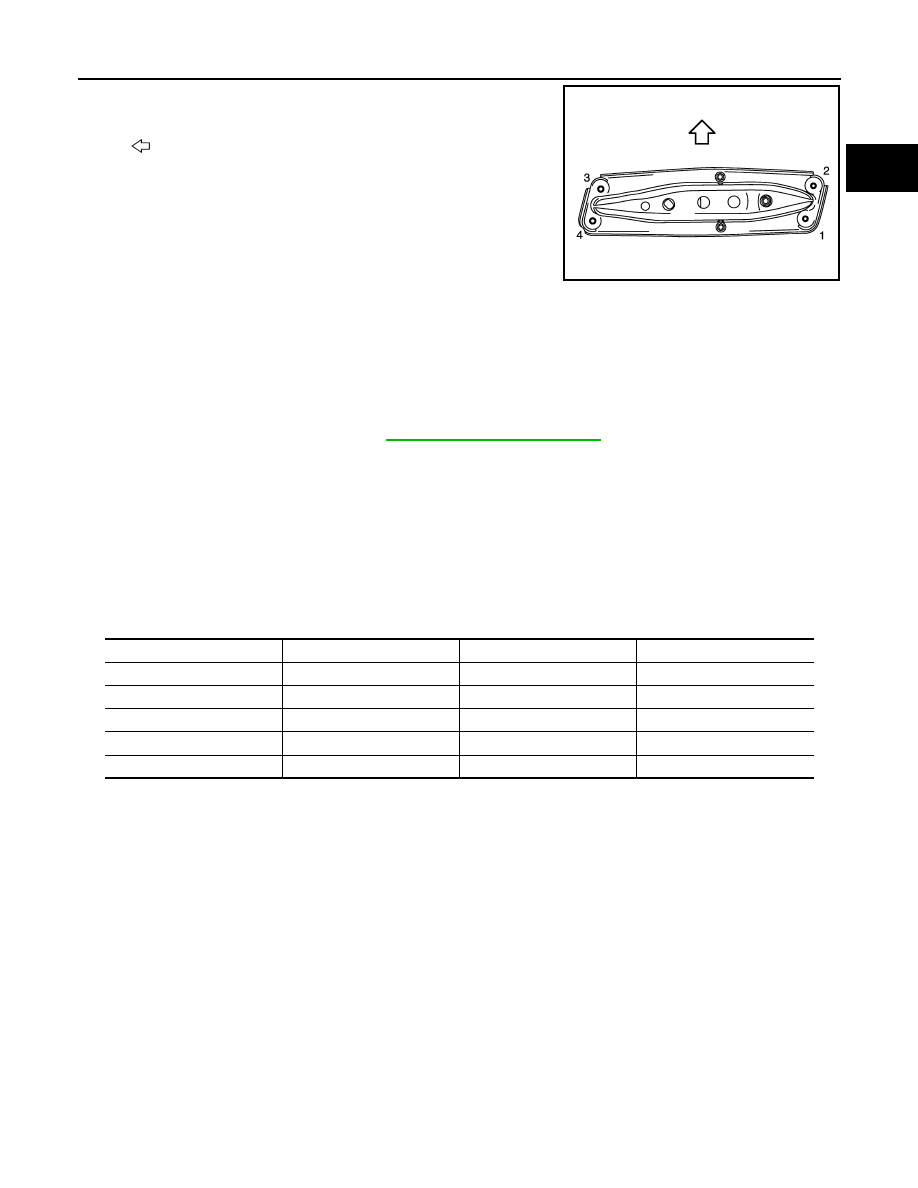
• Tighten rear engine mounting member bolts in numerical order as
shown in the figure.
AWD : Inspection
INFOID:0000000005245160
INSPECTION AFTER INSTALLATION
Inspection for Leakage
The following are procedures for checking fluids leakage, lubricates leakage and exhaust gases leakage.
• Before starting engine, check oil/fluid levels including engine coolant and engine oil. If less than required
quantity, fill to the specified level. Refer to
MA-12, "Fluids and Lubricants"
.
• Use procedure below to check for fuel leakage.
- Turn ignition switch “ON” (with engine stopped). With fuel pressure applied to fuel piping, check for fuel leak-
age at connection points.
- Start engine. With engine speed increased, check again for fuel leakage at connection points.
• Run engine to check for unusual noise and vibration.
• Warm up engine thoroughly to check there is no leakage of fuel, exhaust gases, or any oil/fluids including
engine oil and engine coolant.
• Bleed air from lines and hoses of applicable lines, such as in cooling system.
• After cooling down engine, again check oil/fluid levels including engine oil and engine coolant. Refill to the
specified level, if necessary.
Summary of the inspection items:
*: Transmission/transaxle/CVT fluid, power steering fluid, brake fluid, etc.
: Vehicle front
JPBIA2467ZZ
Items
Before starting engine
Engine running
After engine stopped
Engine coolant
Level
Leakage
Level
Engine oil
Level
Leakage
Level
Other oils and fluid*
Level
Leakage
Level
Fuel
Leakage
Leakage
Leakage
Exhaust gases
—
Leakage
—
Нет комментариевНе стесняйтесь поделиться с нами вашим ценным мнением.
Текст