Infiniti FX35, FX50 (S51). Manual — part 932

EM-28
< REMOVAL AND INSTALLATION >
[VQ35HR]
DRIVE BELT AUTO TENSIONER AND IDLER PULLEY
DRIVE BELT AUTO TENSIONER AND IDLER PULLEY
Exploded View
INFOID:0000000005245125
Removal and Installation
INFOID:0000000005245126
Removal
1.
Remove drive belt. Refer to
.
• Keep auto-tensioner pulley arm locked after drive belt is removed.
2.
Remove auto-tensioner and idler pulley.
• Keep auto-tensioner pulley arm locked to install or remove auto-tensioner.
Installation
Installation is the reverse order of removal.
CAUTION:
If there is damage greater than peeled paint, replace drive belt auto-tensioner.
1.
Front timing chain case
2.
Drive belt auto-tensioner
3.
Idler pulley
4.
Idler pulley
Refer to
for symbols in the figure.
JPBIA0004ZZ

AIR CLEANER AND AIR DUCT
EM-29
< REMOVAL AND INSTALLATION >
[VQ35HR]
C
D
E
F
G
H
I
J
K
L
M
A
EM
N
P
O
AIR CLEANER AND AIR DUCT
Exploded View
INFOID:0000000005245127
Removal and Installation
INFOID:0000000005245128
REMOVAL
1.
Disconnect mass air flow sensor harness connector.
2.
Disconnect PCV hose.
3.
Remove air cleaner case with mass air flow sensor and air duct, disconnecting each joints.
• Add matching marks, if necessary for easier installation.
4.
Remove mass air flow sensor from air cleaner case, if necessary.
CAUTION:
Handle mass air flow sensor with the following cares.
• Never impact mass air flow sensor.
• Never disassemble mass air flow sensor.
• Never touch mass air flow sensor.
INSTALLATION
1.
Air cleaner filter
2.
Holder
3.
Air cleaner case (bank 1)
4.
Air duct (inlet)
5.
Grommet
6.
Air cleaner case (bank 2)
7.
Mass air flow sensor (bank 2)
8.
Clamp
9.
Air duct (bank 2)
10. Clamp
11.
PCV hose
12. Clamp
13. PCV hose
14. Air duct (bank 1)
15. Mass air flow sensor (bank 1)
A.
To electric throttle control actuator
(bank 2)
B.
To electric throttle control actuator
(bank 1)
C.
To rocker cover (bank 2)
Refer to
for symbols in the figure.
JPBIA2324GB

EM-30
< REMOVAL AND INSTALLATION >
[VQ35HR]
AIR CLEANER AND AIR DUCT
Note the following item, and install in the reverse order of removal.
• Align marks. Attach each joint. Screw clamps firmly.
Inspection
INFOID:0000000005245129
INSPECTION AFTER REMOVAL
Inspect air duct and resonator if assembly for crack or tear.
• If damage found, replace air duct and resonator assembly.
Clamp tightening torque
:4.5 N·m (0.46 kg-m, 40 in-lb)
INTAKE MANIFOLD COLLECTOR
EM-31
< REMOVAL AND INSTALLATION >
[VQ35HR]
C
D
E
F
G
H
I
J
K
L
M
A
EM
N
P
O
INTAKE MANIFOLD COLLECTOR
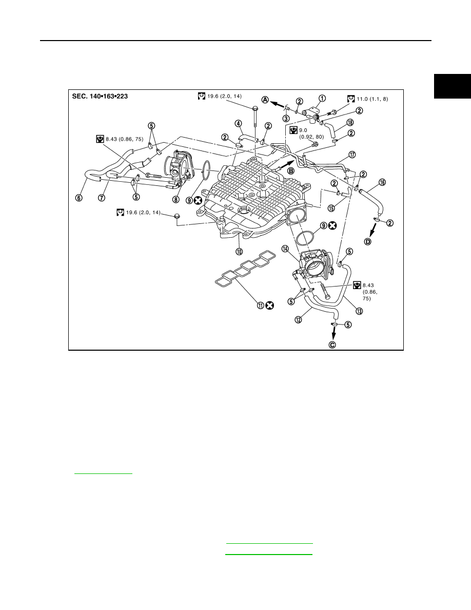
Exploded View
INFOID:0000000005245130
Removal and Installation
INFOID:0000000005245131
REMOVAL
WARNING:
Never drain engine coolant when the engine is hot to avoid the danger of being scalded.
1.
Remove engine cover with power tool. Refer to
.
2.
Remove air cleaner case and air duct. Refer to
3.
Remove electric throttle control actuator as per the following:
a.
Drain engine coolant, or when water hoses are disconnected, attach plug to prevent engine coolant leak-
age.
1.
EVAP canister purge control solenoid
valve
2.
Clamp
3.
EVAP hose
4.
EVAP hose
5.
Clamp
6.
Water hose
7.
Water hose
8.
Electric throttle control actuator
(bank1)
9.
Gasket
10. Intake manifold collector
11.
Gasket
12. Water hose
13. Water hose
14.
Electric throttle control actuator
(bank2)
15. EVAP hose
16. Water hose
17. EVAP tube assembly
18. EVAP hose
A.
To vacuum pipe
B.
To brake booster
C.
To heater pipe
D.
To water outlet (rear)
for symbols in the figure.
JPBIA1900GB
Нет комментариевНе стесняйтесь поделиться с нами вашим ценным мнением.
Текст