Infiniti FX35, FX50 (S51). Manual — part 933
EM-32
< REMOVAL AND INSTALLATION >
[VQ35HR]
INTAKE MANIFOLD COLLECTOR
CAUTION:
• Perform this step when engine is cold.
• Never spill engine coolant on drive belt.
b.
Disconnect water hoses from electric throttle control actuator. When engine coolant is not drained from
radiator, attach plug to water hoses to prevent engine coolant leakage.
c.
Disconnect harness connector.
d.
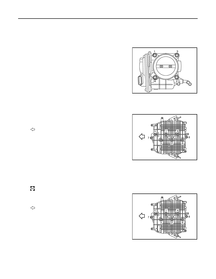
Loosen mounting bolts in reverse order as shown in the figure.
NOTE:
• When removing only intake manifold collector, move electric
throttle control actuator without disconnecting the water hose.
• The figure shows the electric throttle control actuator (bank 1)
viewed from the air duct side.
• Viewed from the air duct side, order of loosening mounting
bolts of electric throttle control actuator (bank 2) is the same
as that of the electric throttle control actuator (bank 1).
CAUTION:
Handle carefully to avoid any impact to electric throttle con-
trol actuator.
4.
Disconnect vacuum hose, PCV hose and EVAP hose from intake manifold collector.
5.
Remove EVAP canister purge volume control solenoid valve and EVAP tube assembly from intake mani-
fold collector.
6.
Loosen mounting bolts and nuts with power tool in the reverse
order as shown in the figure to remove intake manifold collector.
INSTALLATION
Note the following item, and install in the reverse order of removal.
INTAKE MANIFOLD COLLECTOR
• If stud bolts were removed, install them and tighten to the specified torque below.
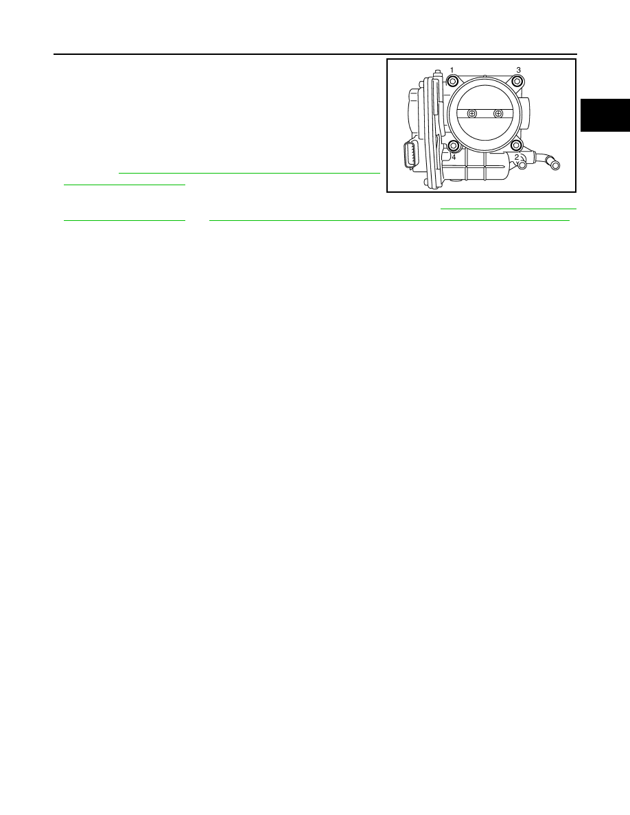
• Tighten mounting bolts and nuts in numerical order as shown in the
figure.
WATER HOSE
• Insert hose by 27 to 32 mm (1.06 to 1.26 in) from connector end.
• Clamp hose at location of 3 to 7 mm (0.12 to 0.28 in) from hose end.
ELECTRIC THROTTLE CONTROL ACTUATOR (BANK 1 AND BANK 2)
JPBIA0011ZZ
: Engine front
JPBIA0012ZZ
: 10.8 N·m (1.1 kg-m, 8 ft-lb)
: Engine front
JPBIA0012ZZ
INTAKE MANIFOLD COLLECTOR
EM-33
< REMOVAL AND INSTALLATION >
[VQ35HR]
C
D
E
F
G
H
I
J
K
L
M
A
EM
N
P
O
• Tighten in numerical order as shown in the figure.
NOTE:
• The figure shows the electric throttle control actuator (bank 1)
viewed from the air duct side.
• Viewed from the air duct side, order of tightening mounting bolts
of electric throttle control actuator (bank 2) is the same as that of
the electric throttle control actuator (bank 1).
• Perform the “Throttle Valve Closed Position Learning” when har-
ness connector of electric throttle control actuator is disconnected.
Refer to
EC-25, "THROTTLE VALVE CLOSED POSITION
.
• Perform the “Idle Air Volume Learning” and “Throttle Valve Closed
Position Learning” when electric throttle control actuator is replaced. Refer to
EC-25, "THROTTLE VALVE CLOSED POSITION LEARNING : Description"
JPBIA0011ZZ
EM-34
< REMOVAL AND INSTALLATION >
[VQ35HR]
INTAKE MANIFOLD
INTAKE MANIFOLD
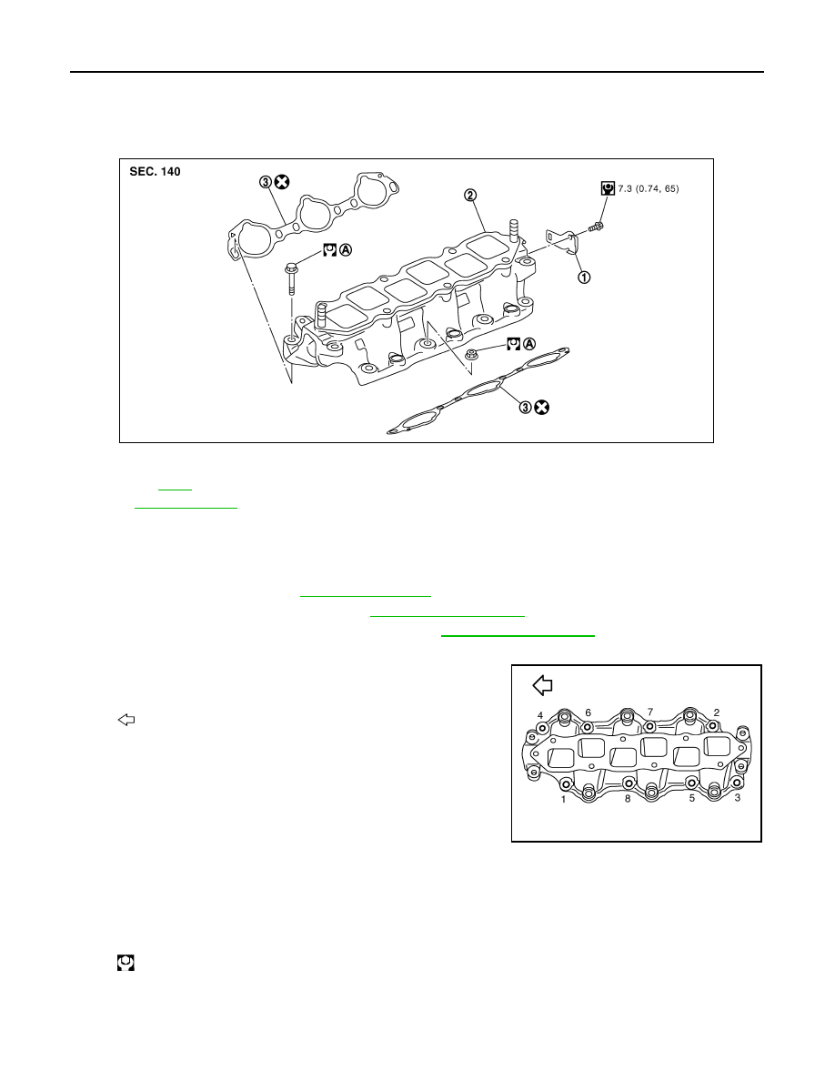
Exploded View
INFOID:0000000005245132
Removal and Installation
INFOID:0000000005245133
REMOVAL
1.
Release fuel pressure. Refer to
.
2.
Remove intake manifold collector. Refer to
3.
Remove fuel tube and fuel injector assembly. Refer to
.
4.
Remove harness bracket.
5.
Loosen mounting bolts and nuts in reverse order as shown in
the figure to remove intake manifold with power tool.
CAUTION:
• Cover engine openings to avoid entry of foreign materi-
als.
• Put a mark on the intake manifold and the cylinder head
with paint before removal because they need installed in
the specified direction.
6.
Remove gaskets.
INSTALLATION
Note the following item, and install in the reverse order of removal.
INTAKE MANIFOLD
• If stud bolts were removed, install them and tighten to the specified torque below.
1.
Harness bracket
2.
Intake manifold
3.
Gasket
A.
Refer to
Refer to
for symbols in the figure.
PBIC5453E
: Engine front
JPBIA0013ZZ
: 10.8 N·m (1.1 kg-m, 8 ft-lb)
INTAKE MANIFOLD
EM-35
< REMOVAL AND INSTALLATION >
[VQ35HR]
C
D
E
F
G
H
I
J
K
L
M
A
EM
N
P
O
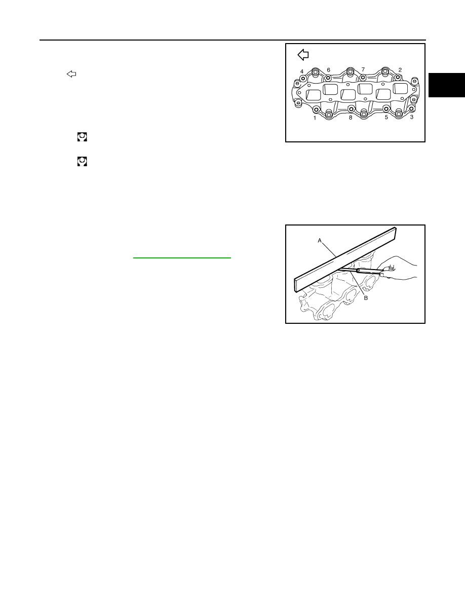
• Tighten all mounting bolts and nuts to the specified torque in two or
more steps in numerical order as shown in the figure.
CAUTION:
Install intake manifold with the marks (put on the intake mani-
fold and the cylinder head before removal) aligned.
Inspection
INFOID:0000000005245134
INSPECTION AFTER REMOVAL
Surface Distortion
• Check the surface distortion of the intake manifold mating surface
with a straightedge (A) and a feeler gauge (B).
• If it exceeds the limit, replace intake manifold.
: Engine front
1st step:
: 7.4 N·m (0.75 kg-m, 5 ft-lb)
2nd step and after:
: 25.5 N·m (2.6 kg-m, 19 ft-lb)
JPBIA0013ZZ
Limit
: Refer to
JPBIA0015ZZ
Нет комментариевНе стесняйтесь поделиться с нами вашим ценным мнением.
Текст