Infiniti FX35, FX50 (S51). Manual — part 1083

FAX-30
< REMOVAL AND INSTALLATION >
[AWD]
FRONT DRIVE SHAFT
2.
Fill serration slot joint sub-assembly (1) with NISSAN genuine
grease or equivalent until the serration slot and ball groove
become full to the brim.
CAUTION:
After applying grease, use a shop cloth to wipe off old
grease that has oozed out.
3.
Install boot and boot bands to shaft.
CAUTION:
• Wrap serration on shaft with tape (A) to protect the boot
from damage.
• Never reuse boot and boot band.
4.
Remove the tape wrapped around the serration on shaft.
5.
Position circular clip on groove at the shaft edge.
CAUTION:
Never reuse circular clip.
NOTE:
Drive joint inserter is recommended when installing circular clip.
6.
Align both center axles of the shaft edge and joint sub-assembly.
Then assemble shaft with circular clip joint sub-assembly.
7.
Install joint sub-assembly (1) to shaft using plastic hammer.
CAUTION:
Confirm that joint sub-assembly is correctly engaged while
rotating drive shaft.
8.
Apply the specified amount of grease into the boot inside from
large diameter side of boot.
9.
Install the boot securely into grooves (indicated by “*” marks)
shown in the figure.
CAUTION:
If grease adheres to the boot mounting surface (indicated
by “*” mark) on the shaft or joint sub-assembly, boot may
come off. Remove all grease from the surface.
10. To prevent from the deformation of the boot, adjust the boot
installation length (L) to the specified value shown below by
inserting the suitable tool into inside of the boot from the large
diameter side of the boot and discharging the inside air.
CAUTION:
• If the boot mounting length is outside the standard, it may cause breakage in the boot.
• Be careful not to touch the inside of the boot with a tip of tool.
JPDIF0008ZZ
Grease amount
: Refer to
.
JPDIF0009ZZ
JPDIF0011ZZ
L
: Refer to
JPDIF0018ZZ
FRONT DRIVE SHAFT
FAX-31
< REMOVAL AND INSTALLATION >
[AWD]
C
E
F
G
H
I
J
K
L
M
A
B
FAX
N
O
P
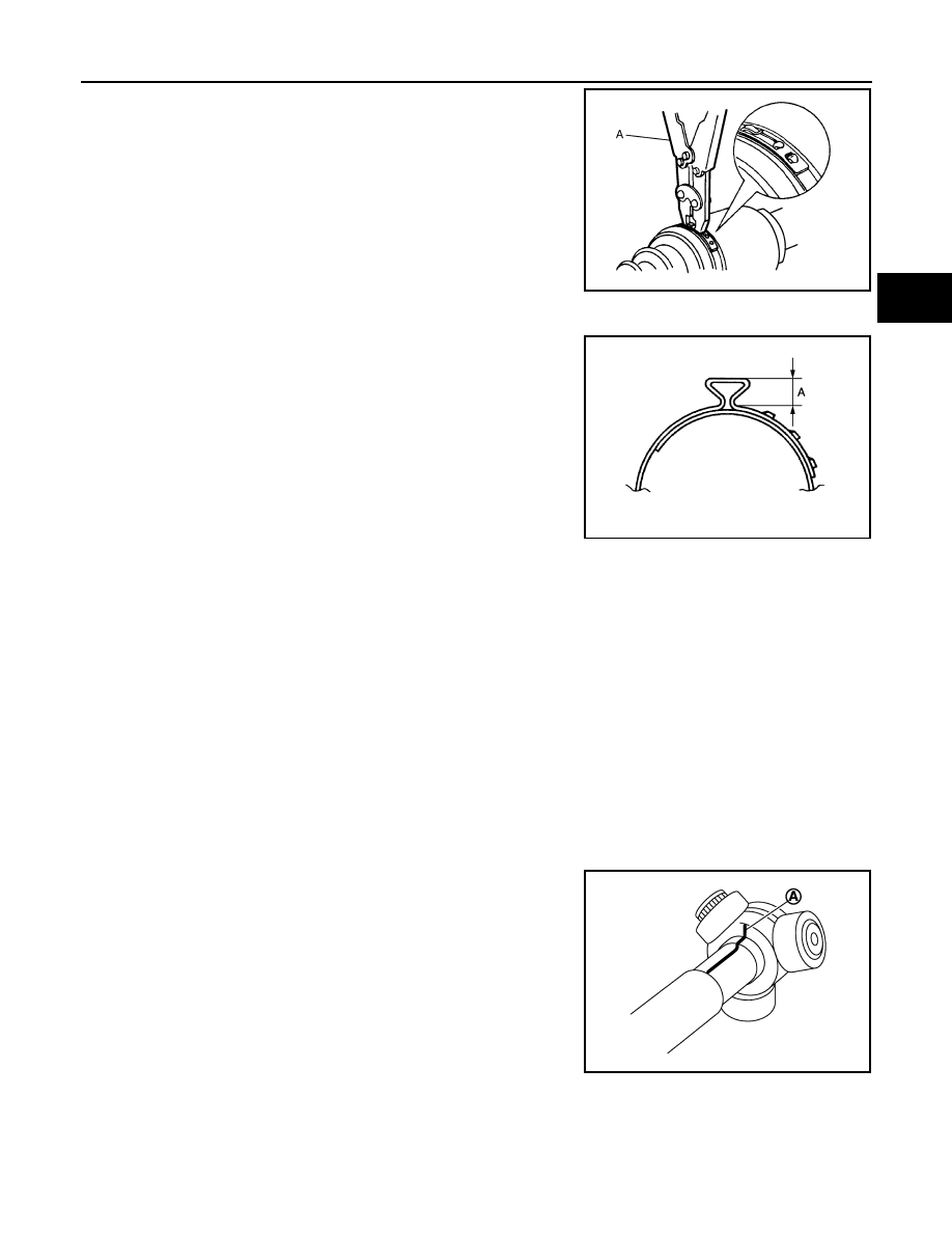
11. Secure the ends of the boot with boot bands using the boot band
crimping tool (A) [SST: KV40107300 (
−
)].
CAUTION:
Never reuse boot band.
NOTE:
Secure boot band so that dimension (A) meets the specification
as shown in the figure.
12. Secure joint sub-assembly and shaft, and then make sure that
they are in the correct position when rotating boot. Install them
with boot band when boot installation positions become incor-
rect.
CAUTION:
Never reuse boot band.
FINAL DRIVE SIDE
FINAL DRIVE SIDE : Disassembly and Assembly
INFOID:0000000005248998
DISASSEMBLY
1.
Fix shaft with a vise.
CAUTION:
Protect shaft when fixing with a vise using aluminum or copper plates.
2.
Remove boot bands, and then remove boot from housing.
3.
If plug needs to be removed, remove with following procedure. (Left side)
• Remove screw and remove plug. (VQ35HR)
• Remove with plastic hammer. (VK50VE)
4.
Remove dust shield. (Right side)
5.
Put matching marks on housing and shaft, and then pull out housing from shaft.
CAUTION:
Use paint or similar substance for matching marks. Never scratch the surfaces.
6.
Put matching marks (A) on the spider assembly and shaft.
CAUTION:
Use paint or similar substance for matching marks. Never
scratch the surfaces.
JPDIF0012ZZ
A
: 7.0 mm (0.276 in) or less
JPDIF0268ZZ
JPDIF0006ZZ
FAX-32
< REMOVAL AND INSTALLATION >
[AWD]
FRONT DRIVE SHAFT
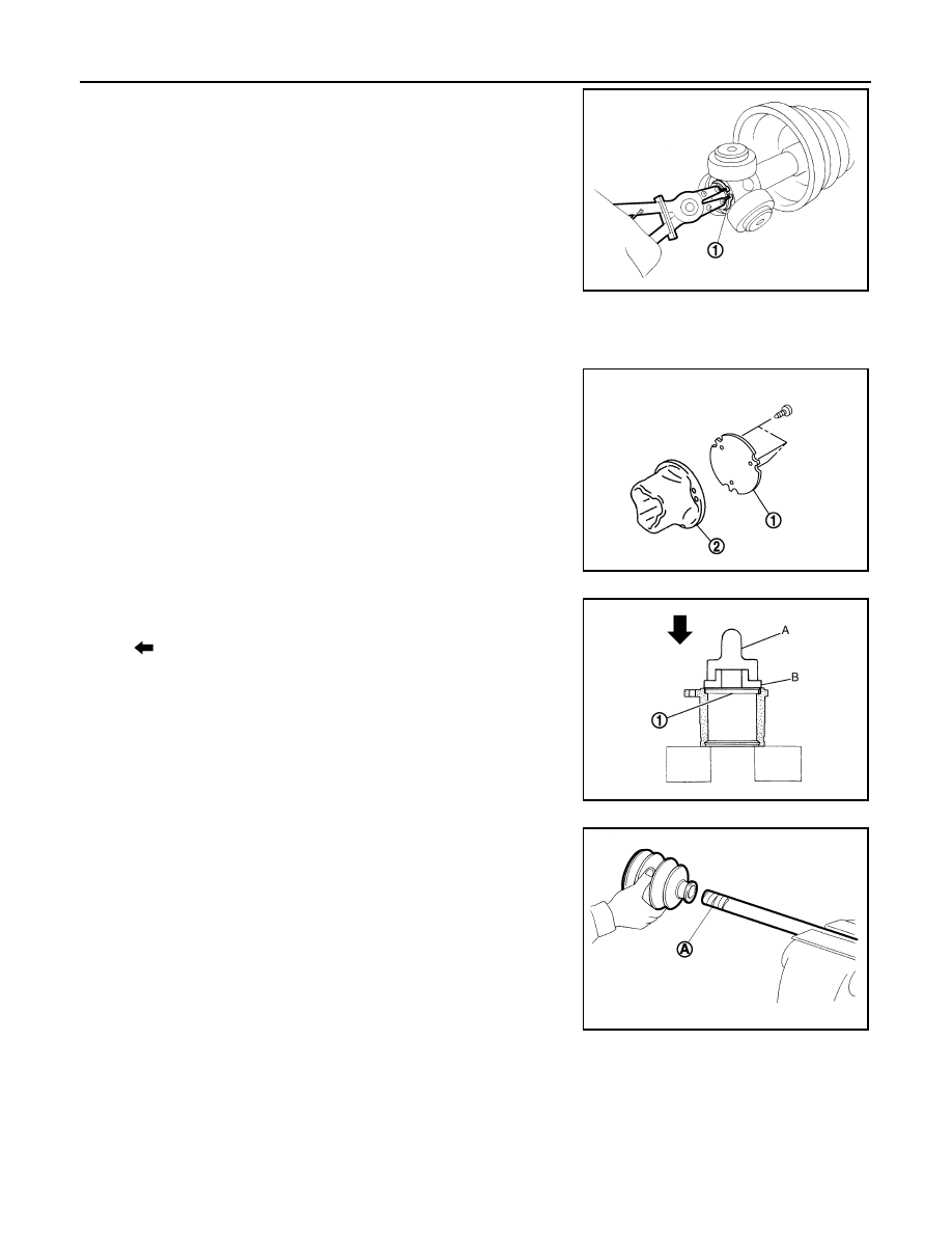
7.
Remove snap ring (1), and then remove spider assembly from
the shaft.
8.
Remove boot from the shaft.
ASSEMBLY
1.
Clean old grease on housing with paper waste.
2.
Plug has been removed, install with the following procedure. (Left side)
• Install plug (1) to housing (2) with screw. (VQ35HR)
• Install plug (1) to housing with drift. (VK50VE)
3.
Install dust shield to housing. (Right side)
CAUTION:
Never reuse dust shield.
4.
Install boot and boot bands to shaft.
CAUTION:
• Wrap serration on shaft with tape (A) to protect boot from
damage.
• Never reuse boot and boot band.
5.
Remove the tape wrapped around the serration on shaft.
JPDIF0014ZZ
JPDIF0161ZZ
: Press
A
: Drift [SST: KV38100500 (
—
)]
B
: Drift [SST: KV38102200 (
—
)]
JPDIF0016ZZ
JPDIF0009ZZ
FRONT DRIVE SHAFT
FAX-33
< REMOVAL AND INSTALLATION >
[AWD]
C
E
F
G
H
I
J
K
L
M
A
B
FAX
N
O
P
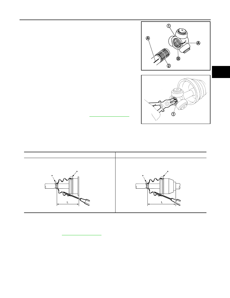
6.
Install the spider assembly (1), align it with the matching marks
(A) on the shaft (2) during the removal, and direct the serration
mounting surface (B) to the shaft.
7.
Secure spider assembly onto shaft with snap ring (1).
CAUTION:
Never reuse snap ring.
8.
Apply the appropriate amount of grease to spider assembly and
sliding surface.
9.
Assemble the housing onto spider assembly, and apply the
specified amount grease.
10. Align matching marks painted when housing was removed.
11. Install the boot securely into grooves (indicated by “*” marks)
shown in the figure.
CAUTION:
If grease adheres to the boot mounting surface (indicated by “*” mark) on shaft or housing, boot
may come off. Remove all grease from the surface.
12. To prevent from deformation of the boot, adjust the boot installation length (L) to the value shown below by
inserting the suitable tool into the inside of boot from the large diameter side of boot and discharging
inside air.
CAUTION:
• If the boot installation length is outside the standard, it may cause breakage in boot.
• Be careful not to touch the inside of the boot with the tip of tool.
13. Install boot bands securely.
CAUTION:
Never reuse boot band.
JPDIF0017ZZ
Grease amount
Left side
Right side
L
: Refer to
.
JPDIF0014ZZ
JPDIF0019ZZ
JPDIF0018ZZ
Нет комментариевНе стесняйтесь поделиться с нами вашим ценным мнением.
Текст