Infiniti FX35, FX50 (S51). Manual — part 1082
FAX-26
< REMOVAL AND INSTALLATION >
[AWD]
FRONT DRIVE SHAFT
FRONT DRIVE SHAFT
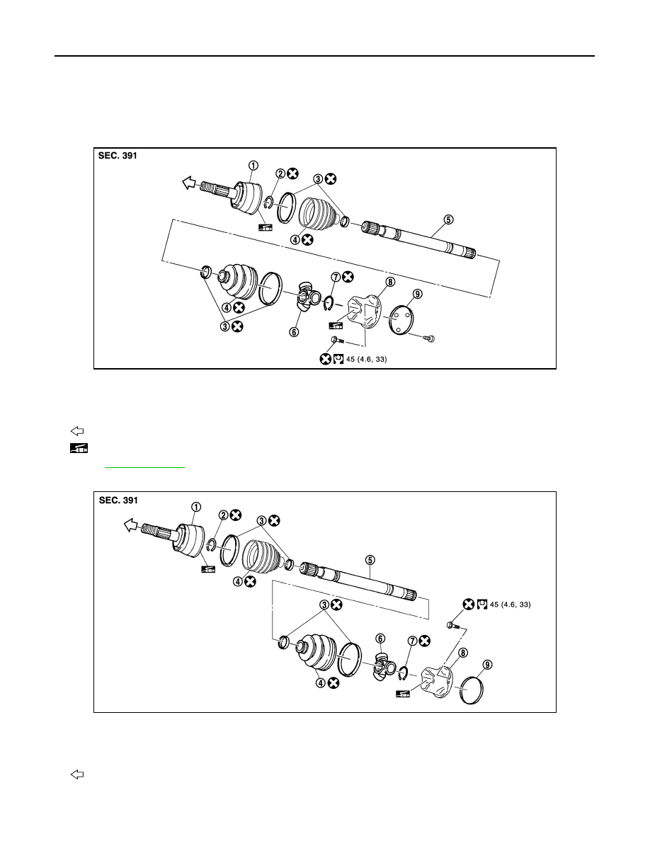
Exploded View
INFOID:0000000005248994
LEFT SIDE
VQ35HR
VK50VE
JPDIF0168GB
1.
Joint sub-assembly
2.
Circular clip
3.
Boot band
4.
Boot
5.
Shaft
6.
Spider assembly
7.
Snap ring
8.
Housing
9.
Plug
: Wheel side
: NISSAN genuine grease or an equivalent.
Refer to
for symbols not described on the above.
JPDIF0191GB
1.
Joint sub-assembly
2.
Circular clip
3.
Boot band
4.
Boot
5.
Shaft
6.
Spider assembly
7.
Snap ring
8.
Housing
9.
Plug
: Wheel side
FRONT DRIVE SHAFT
FAX-27
< REMOVAL AND INSTALLATION >
[AWD]
C
E
F
G
H
I
J
K
L
M
A
B
FAX
N
O
P
RIGHT SIDE
LEFT SIDE
LEFT SIDE : Removal and Installation
INFOID:0000000005248995
REMOVAL
1.
Remove tires with power tool.
2.
Remove wheel sensor and sensor harness. Refer to
BRC-131, "FRONT WHEEL SENSOR : Exploded
.
CAUTION:
Never pull on wheel sensor harness.
3.
Remove brake hose bracket. Refer to
BR-20, "FRONT : Exploded View"
.
4.
Remove caliper assembly mounting bolts with power tool. Hang caliper assembly in a place where it will
not interfere with work. Refer to
BR-43, "BRAKE CALIPER ASSEMBLY (2 PISTON TYPE) : Exploded
BR-47, "BRAKE CALIPER ASSEMBLY (4 PISTON TYPE) : Exploded View"
(4 pis-
ton type).
CAUTION:
Never depress brake pedal while brake caliper is removed.
5.
Remove disc rotor. Refer to
BR-44, "BRAKE CALIPER ASSEMBLY (2 PISTON TYPE) : Removal and
(2 piston type),
BR-48, "BRAKE CALIPER ASSEMBLY (4 PISTON TYPE) : Removal and
(4 piston type).
6.
Remove cotter pin, and then loosen wheel hub lock nut with a power tool. Refer to
.
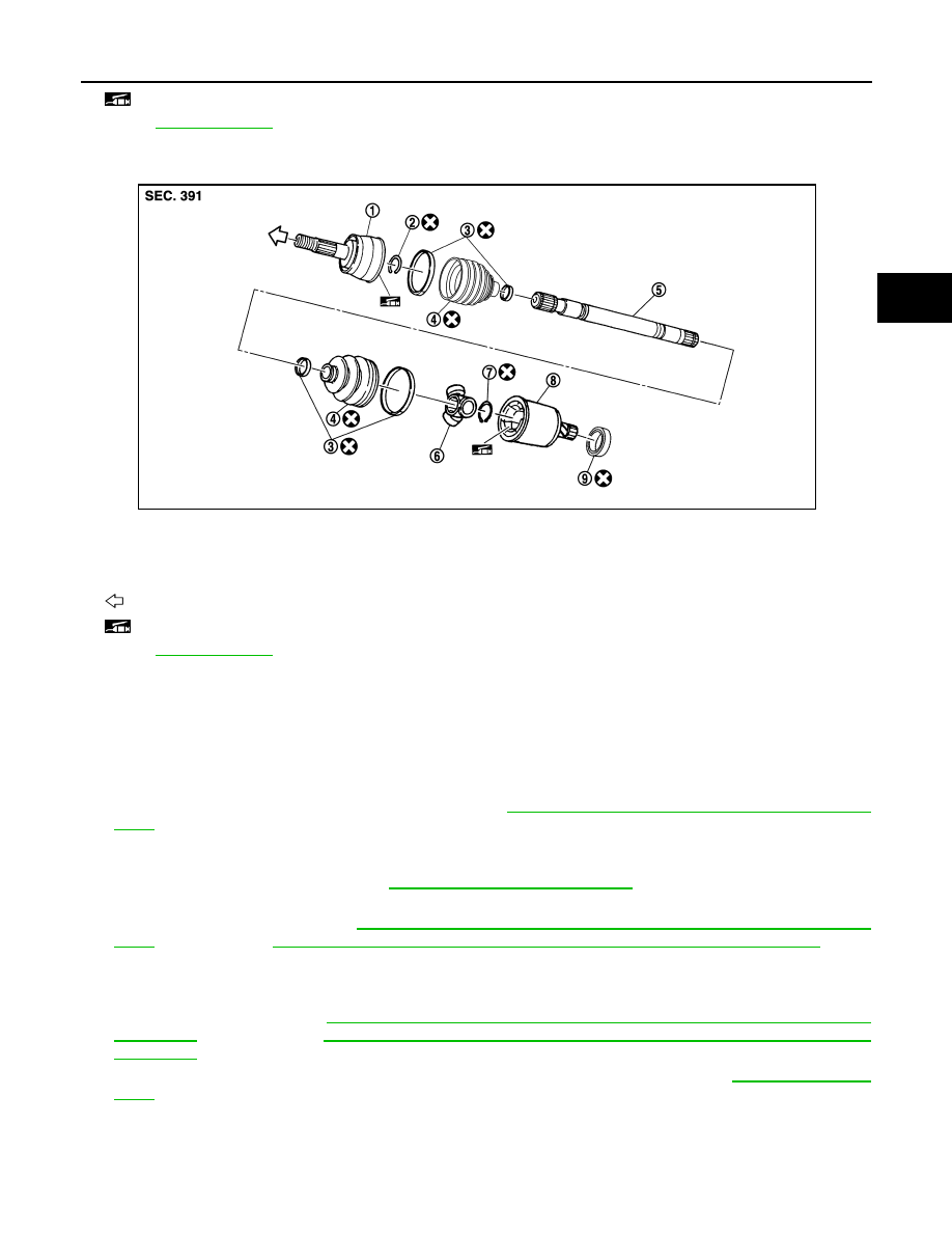
: NISSAN genuine grease or an equivalent.
Refer to
for symbols not described on the above.
1.
Joint sub-assembly
2.
Circular clip
3.
Boot band
4.
Boot
5.
Shaft
6.
Spider assembly
7.
Snap ring
8.
Housing
9.
Dust shield
: Wheel side
: NISSAN genuine grease or an equivalent.
Refer to
for symbols not described on the above.
JPDIF0197ZZ
FAX-28
< REMOVAL AND INSTALLATION >
[AWD]
FRONT DRIVE SHAFT
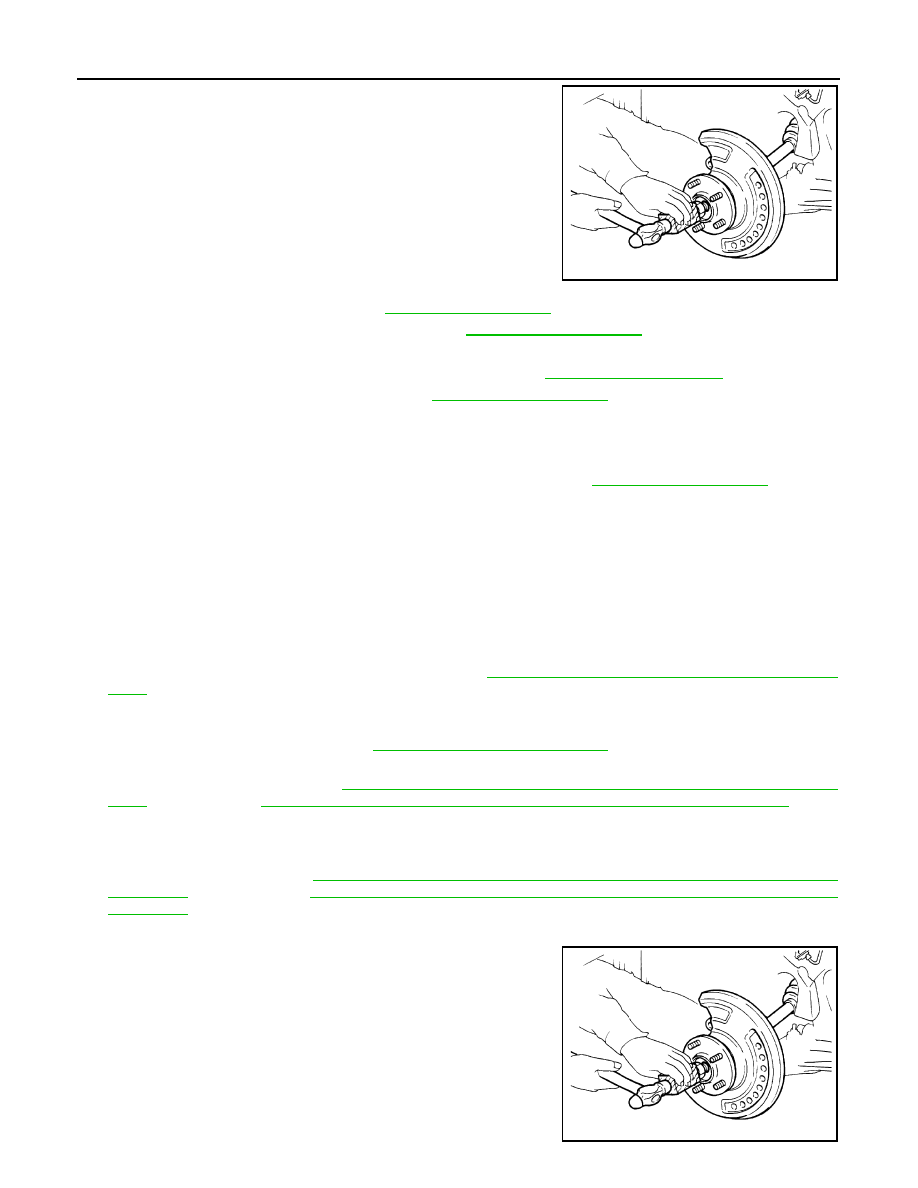
7.
Patch wheel hub lock nut with a piece of wood. Hammer the
wood to disengage wheel hub and bearing assembly from drive
shaft.
CAUTION:
• Never place drive shaft joint at an extreme angle. Also be
careful not to overextend slide joint.
• Never allow drive shaft to hang down without support for
joint sub-assembly, shaft and the other parts.
NOTE:
Use suitable puller if wheel hub and drive shaft cannot be sepa-
rated even after performing the above procedure.
8.
Remove wheel hub lock nut.
9.
Remove steering outer socket. Refer to
10. Separate upper link from steering knuckle. Refer to
.
11. Remove drive shaft from wheel hub and bearing assembly.
12. Remove shock absorber from vehicle with power tool. Refer to
13. Remove under cover with power tool. Refer to
14. Remove mounting bolts, and then remove drive shaft from the front final drive assembly.
INSTALLATION
Note the following, and install in the reverse order of removal.
• Install drive shaft using tightening torque of wheel hub lock nut. Refer to
.
CAUTION:
Be sure to use torque wrench to tighten the wheel hub lock nut. Never use a power tool.
• Never reuse cotter pin.
RIGHT SIDE
RIGHT SIDE : Removal and Installation
INFOID:0000000005248996
REMOVAL
1.
Remove tires with power tool.
2.
Remove wheel sensor and sensor harness. Refer to
BRC-131, "FRONT WHEEL SENSOR : Exploded
.
CAUTION:
Never pull on wheel sensor harness.
3.
Remove brake hose bracket. Refer to
BR-20, "FRONT : Exploded View"
.
4.
Remove caliper assembly mounting bolts with power tool. Hang caliper assembly in a place where it will
not interfere with work. Refer to
BR-43, "BRAKE CALIPER ASSEMBLY (2 PISTON TYPE) : Exploded
BR-47, "BRAKE CALIPER ASSEMBLY (4 PISTON TYPE) : Exploded View"
(4 pis-
ton type).
CAUTION:
Never depress brake pedal while brake caliper is removed.
5.
Remove disc rotor. Refer to
BR-44, "BRAKE CALIPER ASSEMBLY (2 PISTON TYPE) : Removal and
(2 piston type),
BR-48, "BRAKE CALIPER ASSEMBLY (4 PISTON TYPE) : Removal and
(4 piston type).
6.
Remove cotter pin, and then loosen wheel hub lock nut with a power tool.
7.
Patch wheel hub lock nut with a piece of wood. Hammer the
wood to disengage wheel hub and bearing assembly from drive
shaft.
CAUTION:
• Never place drive shaft joint at an extreme angle. Also be
careful not to overextend slide joint.
• Never allow drive shaft to hang down without support for
joint sub-assembly, shaft and the other parts.
NOTE:
Use suitable puller if wheel hub and drive shaft cannot be sepa-
rated even after performing the above procedure.
JPDIG0070ZZ
JPDIG0070ZZ

FRONT DRIVE SHAFT
FAX-29
< REMOVAL AND INSTALLATION >
[AWD]
C
E
F
G
H
I
J
K
L
M
A
B
FAX
N
O
P
8.
Remove wheel hub lock nut.
9.
Remove wheel hub and bearing assembly from steering knuckle. Refer to
10. Remove fender protector. Refer to
EXT-25, "FENDER PROTECTOR : Exploded View"
11. Remove drive shaft from front final drive assembly using the
drive shaft attachment (A) [SST: KV40107500 (
−
)] and a
sliding hammer (commercial service tool) (B) while inserting tip
of the drive shaft attachment between housing and front final
drive assembly.
CAUTION:
Never place drive shaft joint at an extreme angle when
removing drive shaft. Also be careful not to overextend
slide joint.
INSTALLATION
Note the following, and install in the reverse order of removal.
CAUTION:
Always replace final drive oil seal with new one when installing drive shaft. Refer to
• Place the protector (A) [SST: KV38107900 (
−
)] onto final drive
to prevent damage to the oil seal while inserting drive shaft. Slide
drive shaft sliding joint and tap with a hammer to install securely.
CAUTION:
Check that circular clip is completely engaged.
WHEEL SIDE
WHEEL SIDE : Disassembly and Assembly
INFOID:0000000005248997
DISASSEMBLY
1.
Fix shaft with a vise.
CAUTION:
Protect shaft when fixing with a vise using aluminum or copper plates.
2.
Remove boot bands, and then remove boot from joint sub-assembly.
3.
Screw drive shaft puller (commercial service tool) (A) 30 mm
(1.18 in) or more into the thread of joint sub-assembly, and pull
joint sub-assembly from shaft.
CAUTION:
• If joint sub-assembly cannot be removed after five or
more unsuccessful attempts, replace shaft and joint sub
assembly as a set.
• Align sliding hammer and drive shaft and remove them by
pulling directory.
4.
Remove circular clip from shaft.
5.
Remove boot from shaft.
6.
Clean old grease on joint sub-assembly with paper waste while
rotating ball cage.
ASSEMBLY
1.
Clean the old grease on joint sub-assembly with paper waste.
JPDIF0004ZZ
JPDIF0023ZZ
JPDIG0151ZZ
Нет комментариевНе стесняйтесь поделиться с нами вашим ценным мнением.
Текст