Infiniti FX35, FX50 (S51). Manual — part 418

CCS-492
< DTC/CIRCUIT DIAGNOSIS >
[LDW & LDP]
U0405 LDP) ICC CAM CAN CIR1
U0405 LDP) ICC CAM CAN CIR1
DTC Logic
INFOID:0000000005502107
DTC DETECTION LOGIC
DTC CONFIRMATION PROCEDURE
1.
DTC ERASE
Erase the DTC memory of ABS actuator and electric unit (control unit) with CONSULT-III.
>> GO TO 2.
2.
DTC CONFIRMATION
1.
Turn ignition switch ON and wait for 2 seconds or more.
2.
Perform the self-diagnosis of ABS actuator and electric unit (control unit) with CONSULT-III.
Is the DTC “U0405” detected?
YES
>> Refer to
CCS-492, "Diagnosis Procedure"
NO
>> Refer to
GI-36, "Intermittent Incident"
.
Diagnosis Procedure
INFOID:0000000005502108
1.
PERFORM SELF-DIAGNOSIS OF ICC SENSOR INTEGRATED UNIT
Perform ICC sensor integrated unit self-diagnosis with CONSULT-III.
Is any DTC detected?
YES
>> GO TO 2.
NO
>> GO TO 4.
2.
ICC SENSOR INTEGRATED UNIT TROUBLE DIAGNOSIS
Perform trouble diagnosis of ICC sensor integrated unit. Refer to
>> GO TO 3.
3.
ERASE DTC
Erase DTC memory of ABS actuator and electric unit (control unit) with self-diagnosis of CONSULT-III.
Is the DTC “U0405” erased?
YES
>> INSPECTION END
NO
>> Replace ABS actuator and electric unit (control unit).
4.
PROVISIONAL REPLACEMENT OF ICC SENSOR INTEGRATED UNIT
Remove ICC sensor integrated unit. Install a normal ICC sensor integrated unit.
>> GO TO 5.
5.
ERASE DTC
Erase DTC memory of ABS actuator and electric unit (control unit) with self-diagnosis of CONSULT-III.
Is the DTC “U0405” erased?
YES
>> Replace ICC sensor integrated unit.
NO
>> Replace ABS actuator and electric unit (control unit).
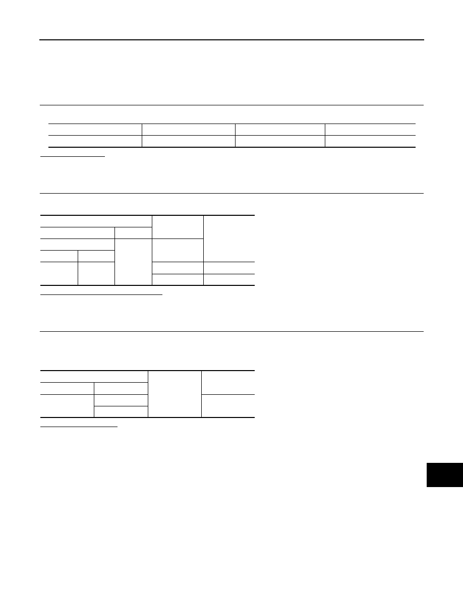
DTC
No.
Trouble diagnosis
name
DTC detecting condition
DTC erase conditions
Possible cause
U0405
LDP) ICC CAM CAN
CIR1
ABS actuator and electric unit (control
unit) detected an error of CAN com-
munication signal that was received
from ICC sensor integrated unit.
Erase DTC with CON-
SULT-III
• ICC sensor integrated unit
• ABS actuator and electric
unit (control unit)

CCS
U1500 LDP) CAM CAN CIR1
CCS-493
< DTC/CIRCUIT DIAGNOSIS >
[LDW & LDP]
C
D
E
F
G
H
I
J
K
L
M
B
N
P
A
U1500 LDP) CAM CAN CIR1
DTC Logic
INFOID:0000000005502109
DTC DETECTION LOGIC
DTC CONFIRMATION PROCEDURE
1.
DTC ERASE
Erase the DTC memory of ABS actuator and electric unit (control unit) with CONSULT-III.
>> GO TO 2.
2.
DTC CONFIRMATION
1.
Turn ignition switch ON and wait for 2 seconds or more.
2.
Perform the self-diagnosis of ABS actuator and electric unit (control unit) with CONSULT-III.
Is the DTC “U1500” detected?
YES
>> Refer to
CCS-493, "Diagnosis Procedure"
NO
>> Refer to
GI-36, "Intermittent Incident"
.
Diagnosis Procedure
INFOID:0000000005502110
1.
PERFORM SELF-DIAGNOSIS OF LANE CAMERA UNIT
Perform self-diagnosis of lane camera unit with CONSULT-III.
Is any DTC detected?
YES
>> GO TO 2.
NO
>> GO TO 4.
2.
LANE CAMERA UNIT TROUBLE DIAGNOSIS
Perform trouble diagnosis of the lane camera unit. Refer to
>> GO TO 3.
3.
ERASE DTC
Erase DTC memory of ABS actuator and electric unit (control unit) with self-diagnosis of CONSULT-III.
Is the DTC “U1500” erased?
YES
>> INSPECTION END
NO
>> Replace ABS actuator and electric unit (control unit).
4.
PROVISIONAL REPLACEMENT OF LANE CAMERA UNIT
Remove the lane camera unit. Install a normal lane camera unit.
>> GO TO 5.
5.
ERASE DTC
Erase DTC memory of ABS actuator and electric unit (control unit) with self-diagnosis of CONSULT-III.
Is the DTC “U1500” erased?
YES
>> Replace the lane camera unit.
NO
>> Replace ABS actuator and electric unit (control unit).
DTC
No.
Trouble diagnosis
name
DTC detecting condition
DTC erase conditions
Possible cause
U1500
LDP) CAM CAN CIR1
ABS actuator and electric unit (control
unit) detected an error of CAN com-
munication signal that was received
from the lane camera unit.
Erase DTC with CON-
SULT-III
• Lane camera unit
• ABS actuator and electric
unit (control unit)

CCS-494
< DTC/CIRCUIT DIAGNOSIS >
[LDW & LDP]
U1501 LDP) CAM CAN CIR2
U1501 LDP) CAM CAN CIR2
DTC Logic
INFOID:0000000005502111
DTC DETECTION LOGIC
DTC CONFIRMATION PROCEDURE
1.
DTC ERASE
Erase the DTC memory of ABS actuator and electric unit (control unit) with CONSULT-III.
>> GO TO 2.
2.
DTC CONFIRMATION
1.
Turn ignition switch ON and wait for 2 seconds or more.
2.
Perform the self-diagnosis of ABS actuator and electric unit (control unit) with CONSULT-III.
Is the DTC “U1501” detected?
YES
>> Refer to
CCS-494, "Diagnosis Procedure"
NO
>> Refer to
GI-36, "Intermittent Incident"
.
Diagnosis Procedure
INFOID:0000000005502112
1.
PERFORM SELF-DIAGNOSIS OF LANE CAMERA UNIT
Perform self-diagnosis of lane camera unit with CONSULT-III.
Is any DTC detected?
YES
>> GO TO 2.
NO
>> GO TO 4.
2.
LANE CAMERA UNIT TROUBLE DIAGNOSIS
Perform trouble diagnosis of the lane camera unit. Refer to
>> GO TO 3.
3.
ERASE DTC
Erase DTC memory of ABS actuator and electric unit (control unit) with self-diagnosis of CONSULT-III.
Is the DTC “U1501” erased?
YES
>> INSPECTION END
NO
>> Replace ABS actuator and electric unit (control unit).
4.
PROVISIONAL REPLACEMENT OF LANE CAMERA UNIT
Remove lane camera unit. Install a normal lane camera unit.
>> GO TO 5.
5.
ERASE DTC
Erase DTC memory of ABS actuator and electric unit (control unit) with self-diagnosis of CONSULT-III.
Is the DTC “U1501” erased?
YES
>> Replace the lane camera unit.
NO
>> Replace ABS actuator and electric unit (control unit).
DTC
No.
Trouble diagnosis
name
DTC detecting condition
DTC erase conditions
Possible cause
U1501
LDP) CAM CAN CIR2
ABS actuator and electric unit (control
unit) detected an error of CAN com-
munication signal that was received
from the lane camera unit.
Erase DTC with CON-
SULT-III
• Lane camera unit
• ABS actuator and electric
unit (control unit)
CCS
POWER SUPPLY AND GROUND CIRCUIT
CCS-495
< DTC/CIRCUIT DIAGNOSIS >
[LDW & LDP]
C
D
E
F
G
H
I
J
K
L
M
B
N
P
A
POWER SUPPLY AND GROUND CIRCUIT
LANE CAMERA UNIT
LANE CAMERA UNIT : Diagnosis Procedure
INFOID:0000000005502113
1.
FUSE INSPECTION
Check that the following fuses are not fusing.
Is the fuse fusing?
YES
>> Replace the blown fuse after repairing the affected circuit.
NO
>> GO TO 2.
2.
CHECK POWER SUPPLY CIRCUIT
Check voltage between the lane camera unit harness connector and ground.
Is the measurement value normal?
YES
>> GO TO 3.
NO
>> Check harness between lane camera unit and fuse.
3.
CHECK GROUND CIRCUIT
1.
Turn ignition switch OFF.
2.
Disconnect the lane camera unit connector.
3.
Check continuity between the lane camera unit harness connectors and ground.
Does continuity exist?
YES
>> Power supply and ground circuit are normal.
NO
>> Repair harness or connector.
Signal name
Connection position
Fuse No.
Capacity
Ignition power supply
FUSE BLOCK (J/B)
3
10 A
Terminals
Condition
Voltage
(Approx.)
(+)
(
−
)
Lane camera unit
Ground
Ignition switch
Connector
Terminal
R8
1
OFF
0 V
ON
Battery voltage
Lane camera unit
Ground
Continuity
Connector
Terminal
R8
6
Existed
12
Нет комментариевНе стесняйтесь поделиться с нами вашим ценным мнением.
Текст