Infiniti FX35, FX50 (S51). Manual — part 419
CCS-496
< DTC/CIRCUIT DIAGNOSIS >
[LDW & LDP]
LDW SWITCH CIRCUIT
LDW SWITCH CIRCUIT
Component Function Check
INFOID:0000000005502114
1.
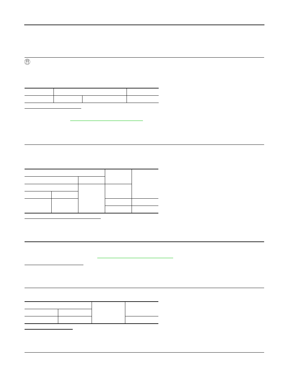
CHECK LDW SWITCH SIGNAL BY CONSULT-III
CONSULT-III DATA MONITOR
1.
Turn the ignition switch ON.
2.
Select “LDW SW” of “LANE CAMERA” data monitor item.
3.
With operating the LDW switch, check the monitor status.
Is the item status normal?
YES
>> LDW switch circuit is normal.
NO
>> Refer to
CCS-496, "Diagnosis Procedure"
Diagnosis Procedure
INFOID:0000000005502115
1.
CHECK LDW SWITCH SIGNAL INPUT
1.
Turn the ignition switch ON.
2.
With operating the LDW switch, check the voltage between the lane camera unit harness connector and
the ground.
Is the measurement value normal?
YES
>> Replace the lane camera unit.
NO
>> GO TO 2.
2.
CHECK LDW SWITCH
1.
Turn ignition switch OFF.
2.
Remove LDW switch.
3.
Check LDW switch. Refer to
CCS-497, "Component Inspection"
.
Is the LDW switch normal?
YES
>> GO TO 3.
NO
>> Replace LDW switch.
3.
CHECK LDW SWITCH GROUND CIRCUIT
Check continuity between LDW switch harness connector terminal and the ground.
Does continuity exist?
YES
>> GO TO 4.
NO
>> Repair harness or connector.
4.
CHECK LDW SWITCH SIGNAL INPUT CIRCUIT FOR OPEN
1.
Disconnect the lane camera unit connector.
Monitor item
Condition
Monitor status
LDW SW
LDW switch
Pressed
⇔
Released
On
⇔
Off
Terminals
Condition
Voltage
(Approx.)
(+)
(
−
)
Lane camera unit
Ground
LDW switch
Connector
Terminal
R8
9
Pressed
0 V
Released
5 V
LDW switch
Ground
Continuity
Connector
Terminal
M29
6
Existed
CCS
LDW SWITCH CIRCUIT
CCS-497
< DTC/CIRCUIT DIAGNOSIS >
[LDW & LDP]
C
D
E
F
G
H
I
J
K
L
M
B
N
P
A
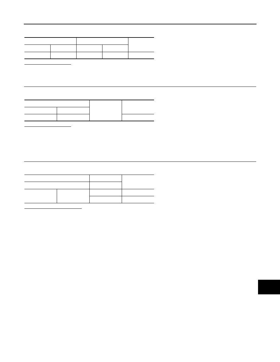
2.
Check continuity between the lane camera unit harness connector and LDW switch harness connector.
Does continuity exist?
YES
>> GO TO 5.
NO
>> Repair the harnesses or connectors.
5.
CHECK LDW SWITCH SIGNAL INPUT CIRCUIT FOR SHORT
Check continuity between the lane camera unit harness connector and ground.
Does continuity exist?
YES
>> Repair the harnesses or connectors.
NO
>> Replace the lane camera unit.
Component Inspection
INFOID:0000000005502116
1.
CHECK LDW SWITCH
Check continuity of LDW switch.
Is the check result normal?
YES
>> LDW switch is normal.
NO
>> Replace LDW switch.
Lane camera unit
LDW switch
Continuity
Connector
Terminal
Connector
Terminal
R8
9
M29
7
Existed
Lane camera unit
Ground
Continuity
Connector
Terminal
R8
9
Not existed
LDW switch
Condition
Continuity
Terminal
LDW switch
6
7
Pressed
Existed
Released
Not existed
CCS-498
< DTC/CIRCUIT DIAGNOSIS >
[LDW & LDP]
LDW ON INDICATOR CIRCUIT
LDW ON INDICATOR CIRCUIT
Component Function Check
INFOID:0000000005502117
1.
CHECK LDW ON INDICATOR BY CONSULT-III
CONSULT-III ACTIVE TEST
1.
Turn the ignition switch ON.
2.
Select “LDW ON IND” of “LANE CAMERA” active test item.
3.
With operating the test item, check the operation.
Does the LDW ON indicator illuminate?
YES
>> LDW ON indicator circuit is normal.
NO
>> Refer to
CCS-498, "Diagnosis Procedure"
Diagnosis Procedure
INFOID:0000000005502118
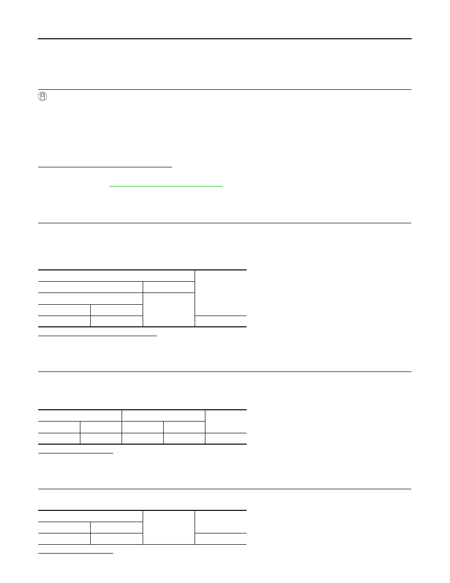
1.
CHECK LDW ON INDICATOR POWER SUPPLY CIRCUIT
1.
Turn ignition switch OFF.
2.
Disconnect LDW switch connector.
3.
Turn ignition switch ON.
4.
Check voltage between LDW switch harness connector and ground.
Is the measurement value normal?
YES
>> GO TO 2.
NO
>> Check harness between fuse and LDW switch.
2.
CHECK LDW ON INDICATOR SIGNAL FOR OPEN
1.
Turn ignition switch OFF.
2.
Disconnect the lane camera unit harness connector.
3.
Check continuity between the lane camera unit harness connector and LDW switch harness connector.
Does continuity exist?
YES
>> GO TO 3.
NO
>> Repair the harnesses or connectors.
3.
CHECK LDW ON INDICATOR SIGNAL CIRCUIT FOR SHORT
Check continuity between the lane camera unit harness connector and ground.
Does continuity exist?
On
: LDW ON indicator illuminates.
Off
: LDW ON indicator is turned OFF.
Terminals
Voltage
(Approx.)
(+)
(
−
)
LDW switch
Ground
Connector
Terminal
M29
3
Battery voltage
Lane camera unit
LDW switch
Continuity
Connector
Terminal
Connector
Terminal
R8
4
M29
2
Existed
Lane camera unit
Ground
Continuity
Connector
Terminal
R8
4
Not existed
CCS
LDW ON INDICATOR CIRCUIT
CCS-499
< DTC/CIRCUIT DIAGNOSIS >
[LDW & LDP]
C
D
E
F
G
H
I
J
K
L
M
B
N
P
A
YES
>> Repair the harnesses or connectors.
NO
>> GO TO 4.
4.
CHECK LDW ON INDICATOR
1.
Connect LDW switch connector.
2.
Turn ignition switch ON.
3.
Apply ground to LDW switch terminal 2.
4.
Check condition of the LDW ON indicator.
Does LDW ON indicator illuminate?
YES
>> Replace the lane camera unit.
NO
>> Replace LDW switch.
Нет комментариевНе стесняйтесь поделиться с нами вашим ценным мнением.
Текст