Infiniti FX35, FX50 (S51). Manual — part 1184

ECM
HAC-133
< ECU DIAGNOSIS INFORMATION >
[AUTOMATIC AIR CONDITIONER]
C
D
E
F
G
H
J
K
L
M
A
B
HAC
N
O
P
63
(BR)
62
(O)
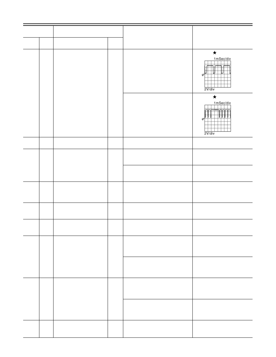
Camshaft position sensor
(bank 2)
Input
[Engine is running]
• Warm-up condition
• Idle speed
NOTE:
The pulse cycle changes depending
on rpm at idle
3.0 - 5.0 V
[Engine is running]
• Engine speed: 2,000 rpm
3.0 - 5.0 V
64
(P)
62
(O)
Exhaust valve timing control
position sensor (bank 2)
Input
[Engine is running]
• Warm-up condition
• Idle speed
NOTE:
The pulse cycle changes depending
on rpm at idle
4.0 - 5.0 V
[Engine is running]
• Warm-up condition
• Engine speed: 2,000 rpm
4.0 - 5.0 V
65
(LG)
128
(B)
VVEL actuator motor relay
abort signal
(VVEL control module)
Output
[Engine is running]
• Warm-up condition
• Idle speed
0 V
66
(GR)
—
Sensor ground
(Power steering pressure sen-
sor/ Refrigerant pressure sen-
sor)
—
—
—
Terminal No.
(Wire color)
Description
Condition
Value
(Approx.)
+
–
Signal name
Input/
Output
JMBIA0045GB
JMBIA0046GB
JMBIA0043GB
JMBIA0044GB
HAC-134
< ECU DIAGNOSIS INFORMATION >
[AUTOMATIC AIR CONDITIONER]
ECM
67
(Y)
68
(B)
Crankshaft position sensor
Input
[Engine is running]
• Warm-up condition
• Idle speed
NOTE:
The pulse cycle changes depending
on rpm at idle
4.0 - 5.0 V
[Engine is running]
• Engine speed: 2,000 rpm
4.0 - 5.0 V
68
(B)
—
Sensor ground
(Crankshaft position sensor)
—
—
—
69
(W)
70
(B)
Manifold pressure sensor
(This sensor is not for control-
ling the engine system, nor for
the on board diagnosis.)
Input
[Engine is running]
• Warm-up condition
• Idle speed
1.2 V
[Engine is running]
• Warm-up condition
• Engine speed: 2,000 rpm
1.5 V
70
(B)
—
Sensor ground
[Battery current sensor/ EVAP
control system pressure sen-
sor/ Manifold pressure sensor]
—
—
—
71
(R)
—
Sensor ground
[Throttle position sensor (bank
1)]
—
—
—
72
(Y)
—
Sensor ground
[Throttle position sensor (bank
2)]
—
—
—
73
(L)
71
(R)
Throttle position sensor 1
(bank 1)
Input
[Ignition switch: ON]
• Engine: Stopped
• Selector lever: D position
• Accelerator pedal: Fully released
More than 0.36 V
[Ignition switch: ON]
• Engine: Stopped
• Selector lever: D position
• Accelerator pedal: Fully depressed
Less than 4.75 V
74
(R)
72
(Y)
Throttle position sensor 2
(bank 2)
Input
[Ignition switch: ON]
• Engine: Stopped
• Selector lever: D position
• Accelerator pedal: Fully released
Less than 4.75 V
[Ignition switch: ON]
• Engine: Stopped
• Selector lever: D position
• Accelerator pedal: Fully depressed
More than 0.36 V
76
(G)
70
(B)
Battery current sensor
Input
[Engine is running]
• Battery: Fully charged*
2
• Idle speed
2.6 - 3.5 V
Terminal No.
(Wire color)
Description
Condition
Value
(Approx.)
+
–
Signal name
Input/
Output
JMBIA0041GB
JMBIA0042GB

ECM
HAC-135
< ECU DIAGNOSIS INFORMATION >
[AUTOMATIC AIR CONDITIONER]
C
D
E
F
G
H
J
K
L
M
A
B
HAC
N
O
P
77
(B)
72
(Y)
Throttle position sensor 1
(bank 2)
Input
[Ignition switch: ON]
• Engine: Stopped
• Selector lever: D position
• Accelerator pedal: Fully released
More than 0.36 V
[Ignition switch: ON]
• Engine: Stopped
• Selector lever: D position
• Accelerator pedal: Fully depressed
Less than 4.75 V
78
(Y)
71
(R)
Throttle position sensor 2
(bank 1)
Input
[Ignition switch: ON]
• Engine: Stopped
• Selector lever: D position
• Accelerator pedal: Fully released
Less than 4.75 V
[Ignition switch: ON]
• Engine: Stopped
• Selector lever: D position
• Accelerator pedal: Fully depressed
More than 0.36 V
80
(GR)
70
(B)
EVAP control system pressure
sensor
Input
[Ignition switch: ON]
1.8 - 4.8 V
81
(V)
128
(B)
A/F sensor 1 (bank 1)
Input
[Ignition switch: ON]
2.2 V
82
(LG)
128
(B)
A/F sensor 1 (bank 1)
Input
[Engine is running]
• Warm-up condition
• Engine speed: 2,000 rpm
1.8 V
Output voltage varies with air fuel
ratio.
83
(SB)
66
(GR)
Power steering pressure sen-
sor
Output
[Engine is running]
• Steering wheel: Being turned
0.5 - 4.5 V
[Engine is running]
• Steering wheel: Not being turned
0.4 - 0.8 V
84
(B)
71
(R)
Sensor power supply
[Throttle position sensor (bank
1)]
—
[Ignition switch: ON]
5 V
85
(Y)
128
(B)
A/F sensor 1 (bank 2)
Input
[Ignition switch: ON]
2.2 V
86
(O)
128
(B)
A/F sensor 1 (bank 2)
Input
[Engine is running]
• Warm-up condition
• Engine speed: 2,000 rpm
1.8 V
Output voltage varies with air fuel
ratio.
87
(R)
68
(B)
Sensor power supply
(Crankshaft position sensor)
—
[Ignition switch: ON]
5 V
88
(Y)
62
(O)
Sensor power supply
[Camshaft position sensor
(bank 2)/ Exhaust valve timing
control position sensor (bank
2)]
—
[Ignition switch: ON]
5 V
89
(P)
—
CAN communication line
(VVEL control module)
Input/
Output
—
—
90
(G)
66
(GR)
Refrigerant pressure sensor
Input
[Engine is running]
• Warm-up condition
• Both A/C switch and blower fan mo-
tor switch: ON (Compressor oper-
ates)
1.0 - 4.0 V
91
(R)
58
(B)
Sensor power supply
[Camshaft position sensor
(bank 1)/ Exhaust valve timing
control position sensor (bank
1)]
—
[Ignition switch: ON]
5 V
Terminal No.
(Wire color)
Description
Condition
Value
(Approx.)
+
–
Signal name
Input/
Output
HAC-136
< ECU DIAGNOSIS INFORMATION >
[AUTOMATIC AIR CONDITIONER]
ECM
92
(W)
66
(GR)
Sensor power supply
(Power steering pressure sen-
sor/ Refrigerant pressure sen-
sor)
—
[Ignition switch: ON]
5 V
93
(LG)
—
CAN communication line
(VVEL control module)
Input/
Output
—
—
95
(Y)
70
(B)
Sensor power supply
[Battery current sensor/ EVAP
control system pressure sen-
sor/ Manifold pressure sensor]
—
[Ignition switch: ON]
5 V
96
(L)
72
(Y)
Sensor power supply
[Throttle position sensor (bank
2)]
—
[Ignition switch: ON]
5 V
97
(R)
128
(B)
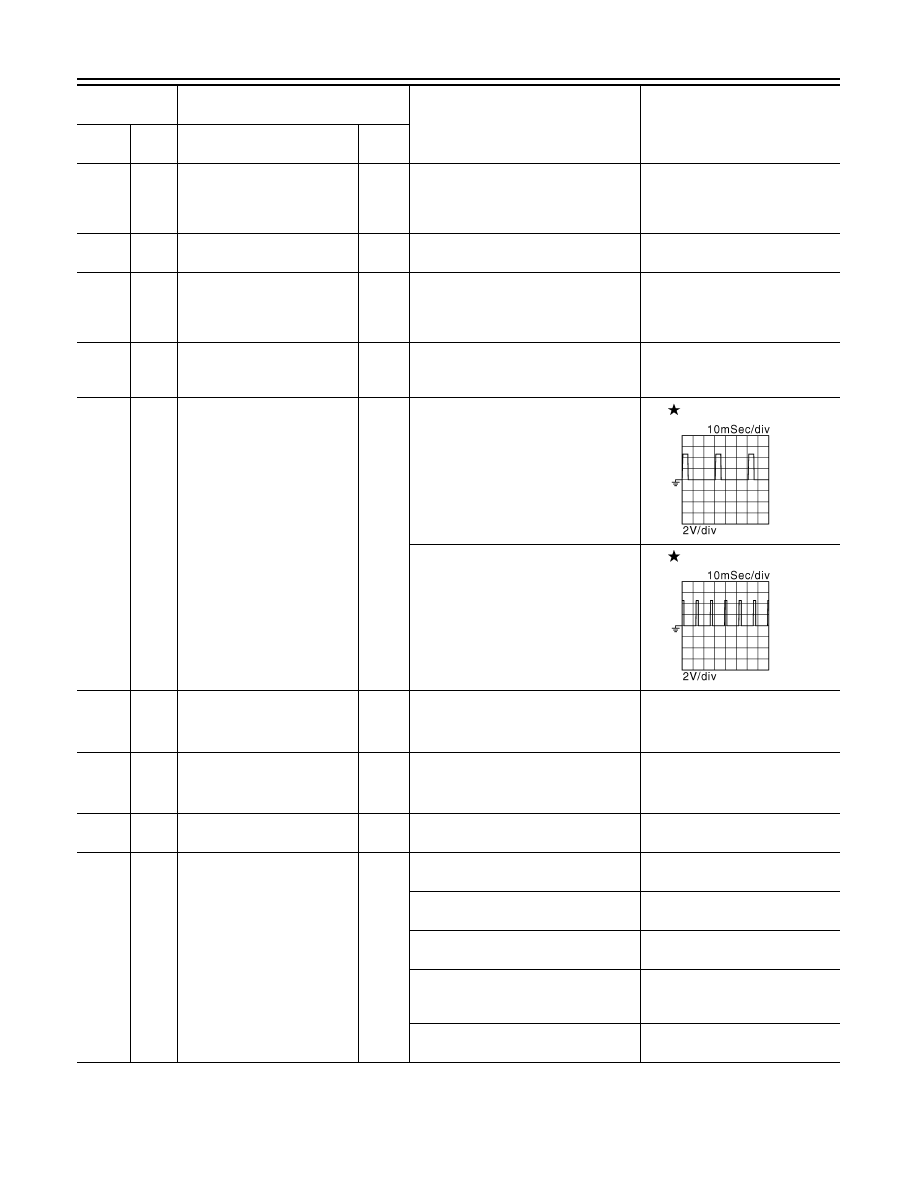
Engine speed output signal
Output
[Engine is running]
• Warm-up condition
• Idle speed
NOTE:
The pulse cycle changes depending
on rpm at idle
1 V
[Engine is running]
• Engine speed is 2,000 rpm
1 V
99
(L)*
3
(G)*
4
115
(GR)
Sensor power supply
(Accelerator pedal position
sensor 2)
—
[Ignition switch: ON]
5 V
100
(G)*
3
(L)*
4
119
(W)
Sensor power supply
(Accelerator pedal position
sensor 1)
—
[Ignition switch: ON]
5 V
101
(P)
—
CAN communication line
Input/
Output
—
—
102
(SB)
111
(V)
ASCD steering switch
Input
[Ignition switch: ON]
• ASCD steering switch: OFF
4 V
[Ignition switch: ON]
• MAIN switch: Pressed
0 V
[Ignition switch: ON]
• CANCEL switch: Pressed
1 V
[Ignition switch: ON]
• RESUME/ACCELERATE switch:
Pressed
3 V
[Ignition switch: ON]
• SET/COAST switch: Pressed
2 V
Terminal No.
(Wire color)
Description
Condition
Value
(Approx.)
+
–
Signal name
Input/
Output
JMBIA0076GB
JMBIA0077GB
Нет комментариевНе стесняйтесь поделиться с нами вашим ценным мнением.
Текст