Infiniti FX35, FX50 (S51). Manual — part 590
FRONT OIL SEAL
DLN-195
< REMOVAL AND INSTALLATION >
[REAR FINAL DRIVE: R200]
C
E
F
G
H
I
J
K
L
M
A
B
DLN
N
O
P
8.
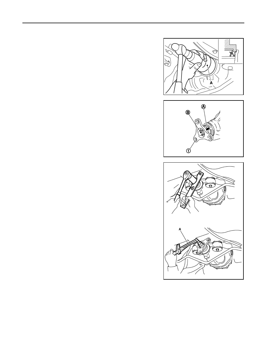
Measure the total preload with the preload gauge (A) [SST:
ST3127S000 (J-25765-A)].
NOTE:
Record the preload measurement.
9.
Put matching mark (B) on the end of the drive pinion. The
matching mark (B) should be in line with the matching mark (A)
on companion flange (1).
CAUTION:
For matching mark, use paint. Never damage companion
flange and drive pinion.
NOTE:
The matching mark (A) on the final drive companion flange (1)
indicates the maximum vertical runout position.
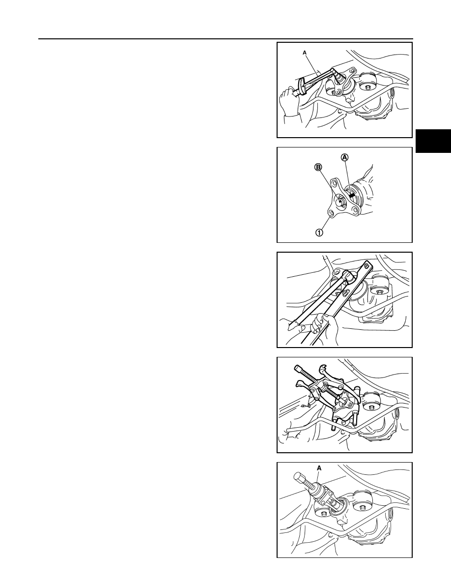
10. Remove drive pinion lock nut using the flange wrench.
11. Remove companion flange using pullers.
12. Remove front oil seal using the puller (A) [SST: KV381054S0 (J-
34286)].
JSDIA0015ZZ
JSDIA0016ZZ
JSDIA0021ZZ
JSDIA0022ZZ
PDIA0980E
DLN-196
< REMOVAL AND INSTALLATION >
[REAR FINAL DRIVE: R200]
FRONT OIL SEAL
INSTALLATION
1.
Apply multi-purpose grease to front oil seal lips.
2.
Install front oil seal using the drift (A) [SST: ST30720000 (J-
25405)] as shown in figure.
CAUTION:
• Never reuse oil seal.
• Never incline oil seal when installing.
3.
Align the matching mark (B) of drive pinion with the matching
mark (A) of companion flange (1), and then install the compan-
ion flange (1).
4.
Apply anti-corrosion oil to the thread and seat of new drive pin-
ion lock nut, and temporarily tighten drive pinion lock nut to drive
pinion.
CAUTION:
Never reuse drive pinion lock nut.
5.
Tighten drive pinion lock nut within the limits of specified torque
so as to keep the pinion bearing preload within a standard val-
ues.
CAUTION:
• Adjust to the lower limit of the drive pinion lock nut tight-
ening torque first.
• If the preload torque exceeds the specified value, replace
collapsible spacer and tighten it again to adjust. Never
loosen drive pinion lock nut to adjust the preload torque.
PDIA0752J
JSDIA0016ZZ
A
: Preload gauge [SST: ST3127S000 (J-25765-A)]
Standard
Total preload torque
: A value that add 0.1 – 0.4
N·m (0.01 – 0.04 kg-m, 0.1 –
0.3 in-lb) to the measured
value before removing.
JSDIA0023ZZ
FRONT OIL SEAL
DLN-197
< REMOVAL AND INSTALLATION >
[REAR FINAL DRIVE: R200]
C
E
F
G
H
I
J
K
L
M
A
B
DLN
N
O
P
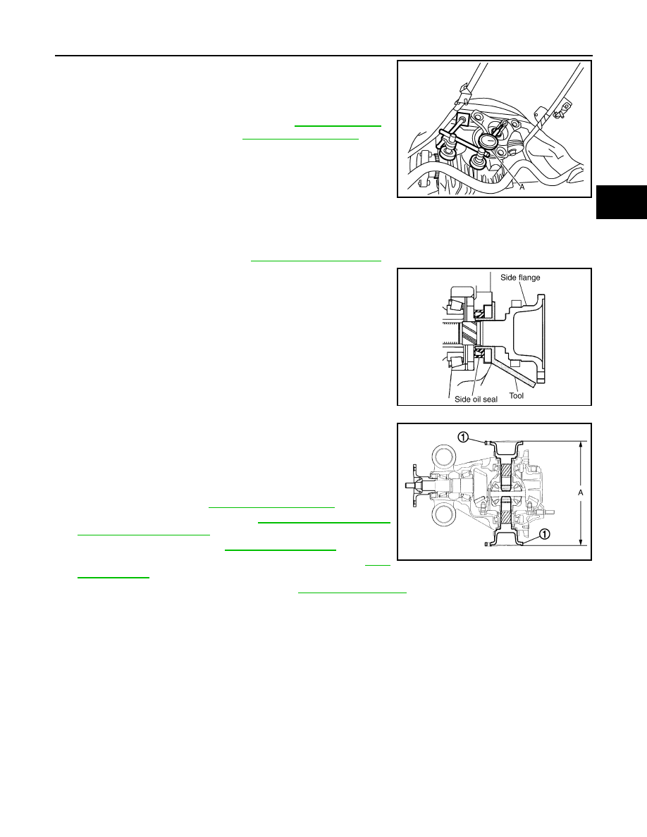
6.
Set a dial indicator (A) vertically to the tip of the drive pinion.
7.
Rotate drive pinion to check for runout.
• If the runout value is still outside of the limit after the phase
has been changed, possible causes are an assembly malfunc-
tion of drive pinion and pinion bearing and malfunction of pin-
ion bearing. Check for these items and repair if necessary.
8.
Make a stamping for identification of front oil seal replacement
frequency. Refer to “Identification stamp of replacement frequency of front oil seal”.
CAUTION:
Make a stamping after replacing front oil seal.
9.
Install rear propeller shaft. Refer to
10. Install side flange with the following procedure.
a.
Attach the protector [SST: KV38107900 (J-39352)] to side oil
seal.
b.
After the side flange is inserted and the serrated part of side
gear has engaged the serrated part of flange, remove the pro-
tector.
c.
Put a suitable drift on the center of side flange, then drive it until
sound changes.
NOTE:
When installation is completed, driving sound of the side flange
turns into a sound that seems to affect the whole final drive.
d.
Confirm that the dimension of the side flange (1) installation
measurement (A) in the figure comes into the following.
11. Install drive shaft. Refer to
12. Install rear wheel sensor. Refer to
.
13. Install center muffler. Refer to
.
14. Refill gear oil to the final drive and check oil level. Refer to
15. Check the final drive for oil leakage. Refer to
.
AWD
Limit
Drive pinion runout
: Refer to
JSDIA0043ZZ
SDIA0822E
Standard
A
: 326 – 328 mm (12.83 – 12.91 in)
JSDIA0106ZZ
DLN-198
< REMOVAL AND INSTALLATION >
[REAR FINAL DRIVE: R200]
FRONT OIL SEAL
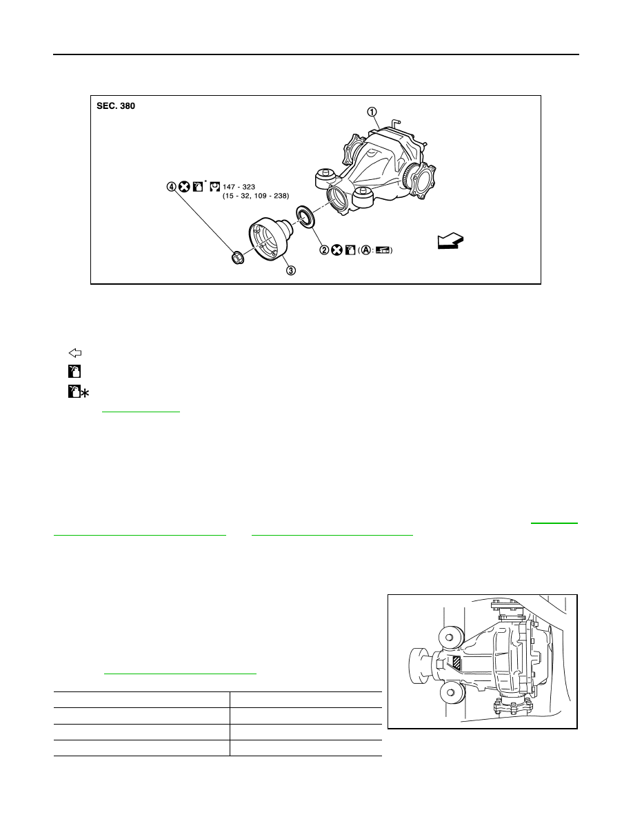
AWD : Exploded View
INFOID:0000000005249227
AWD : Removal and Installation
INFOID:0000000005249228
REMOVAL
CAUTION:
Verify identification stamp of replacement frequency put in the lower part of gear carrier to determine
replacement for collapsible spacer when replacing front oil seal. Refer to “Identification stamp of
replacement frequency of front oil seal”. If collapsible spacer replacement is necessary, remove final
drive assembly and disassemble it to replace front oil seal and collapsible spacer. Refer to
"AWD : Removal and Installation"
and
NOTE:
The reuse of collapsible spacer is prohibited in principle. However, it is reusable on a one-time basis
only in cases when replacing front oil seal.
Identification stamp of replacement frequency of front oil seal
• The diagonally shaded area in the figure shows stamping point for
replacement frequency of front oil seal.
• The following table shows if collapsible spacer replacement is
needed before replacing front oil seal.
When collapsible spacer replacement is required, disassemble
final drive assembly to replace collapsible spacer and front oil seal.
Refer to
.
CAUTION:
Make a stamping after replacing front oil seal.
1.
Final drive assembly
2.
Front oil seal
3.
Companion flange
4.
Drive pinion lock nut
A.
Oil seal lip
: Vehivle front
: Apply gear oil.
: Apply anti-corrosion oil.
Refer to
for symbols not described above.
JPDID0232GB
Stamp
collapsible spacer replacement
No stamp
Not required
“0” or “0” on the far right of stamp
Required
“01” or “1” on the far right of stamp
Not required
PDIA0976E
Нет комментариевНе стесняйтесь поделиться с нами вашим ценным мнением.
Текст