Infiniti FX35, FX50 (S51). Manual — part 589
PREPARATION
DLN-191
< PREPARATION >
[REAR FINAL DRIVE: R200]
C
E
F
G
H
I
J
K
L
M
A
B
DLN
N
O
P
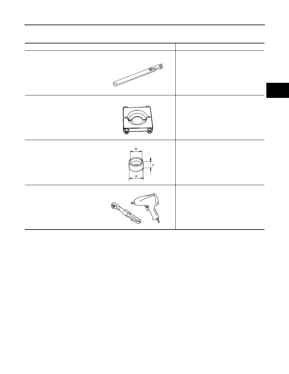
Commercial Service Tools
INFOID:0000000005249220
Tool name
Description
Flange wrench
Removing and installing drive pinion lock nut
Replacer
Removing pinion rear bearing inner race
Spacer
a: 60 mm (2.36 in) dia.
b: 36 mm (1.42 in) dia.
c: 30 mm (1.18 in)
Installing pinion front bearing inner race
Power tool
Loosening bolts and nuts
NT035
ZZA0700D
ZZA1133D
PBIC0190E
DLN-192
< PERIODIC MAINTENANCE >
[REAR FINAL DRIVE: R200]
REAR DIFFERENTIAL GEAR OIL
PERIODIC MAINTENANCE
REAR DIFFERENTIAL GEAR OIL
Inspection
INFOID:0000000005249222
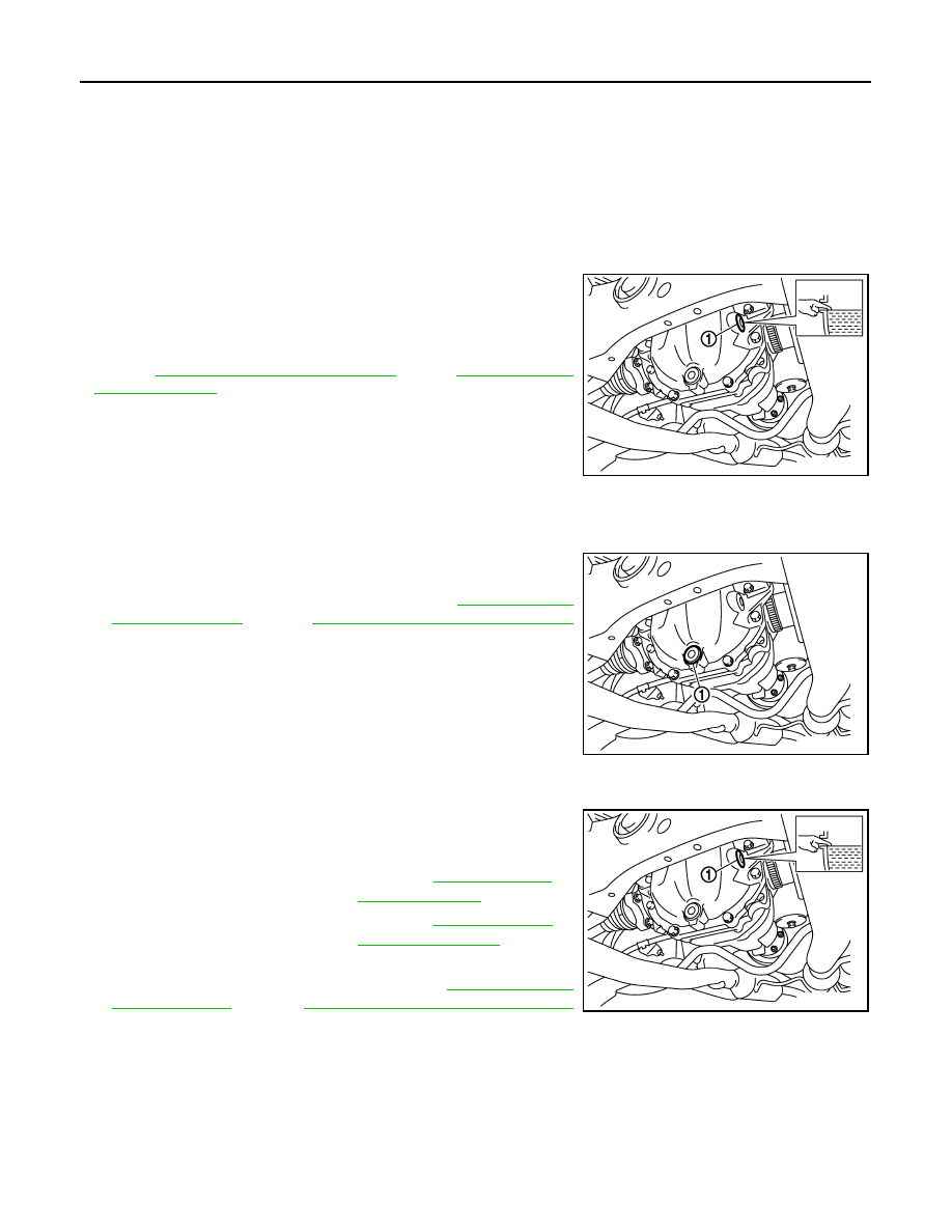
OIL LEAKAGE
• Make sure that oil is not leaking from final drive assembly or around it.
OIL LEVEL
• Remove filler plug (1) and check oil level from filler plug mounting
hole as shown in the figure.
CAUTION:
Never start engine while checking oil level.
• Set a gasket on filler plug (1) and install it on final drive assembly.
DLN-211, "2WD : Exploded View"
(AWD).
CAUTION:
Never reuse gasket.
Draining
INFOID:0000000005249223
1.
Stop engine.
2.
Remove drain plug (1) and drain gear oil.
3.
Set a gasket on drain plug (1) and install it to final drive assem-
bly and tighten to the specified torque. Refer to
(2WD),
DLN-224, "AWD : Exploded View"
(AWD).
CAUTION:
Never reuse gasket.
Refilling
INFOID:0000000005249224
1.
Remove filler plug (1). Fill with new gear oil until oil level reaches
the specified level near filler plug mounting hole.
2.
After refilling oil, check oil level. Set a gasket to filler plug (1),
then install it to final drive assembly. Refer to
DLN-224, "AWD : Exploded View"
(AWD).
CAUTION:
Never reuse gasket.
JPDID0190ZZ
JPDID0191ZZ
Oil grade and viscosity
: Refer to
.
Oil capacity
: Refer to
JPDID0190ZZ
FRONT OIL SEAL
DLN-193
< REMOVAL AND INSTALLATION >
[REAR FINAL DRIVE: R200]
C
E
F
G
H
I
J
K
L
M
A
B
DLN
N
O
P
REMOVAL AND INSTALLATION
FRONT OIL SEAL
2WD
2WD : Exploded View
INFOID:0000000005249225
2WD : Removal and Installation
INFOID:0000000005249226
REMOVAL
CAUTION:
Verify identification stamp of replacement frequency put in the lower part of gear carrier to determine
replacement for collapsible spacer when replacing front oil seal. Refer to “Identification stamp of
replacement frequency of front oil seal”. If collapsible spacer replacement is necessary, remove final
drive assembly and disassemble it to replace front oil seal and collapsible spacer. Refer to
"2WD : Removal and Installation"
.
NOTE:
The reuse of collapsible spacer is prohibited in principle. However, it is reusable on a one-time basis
only in cases when replacing front oil seal.
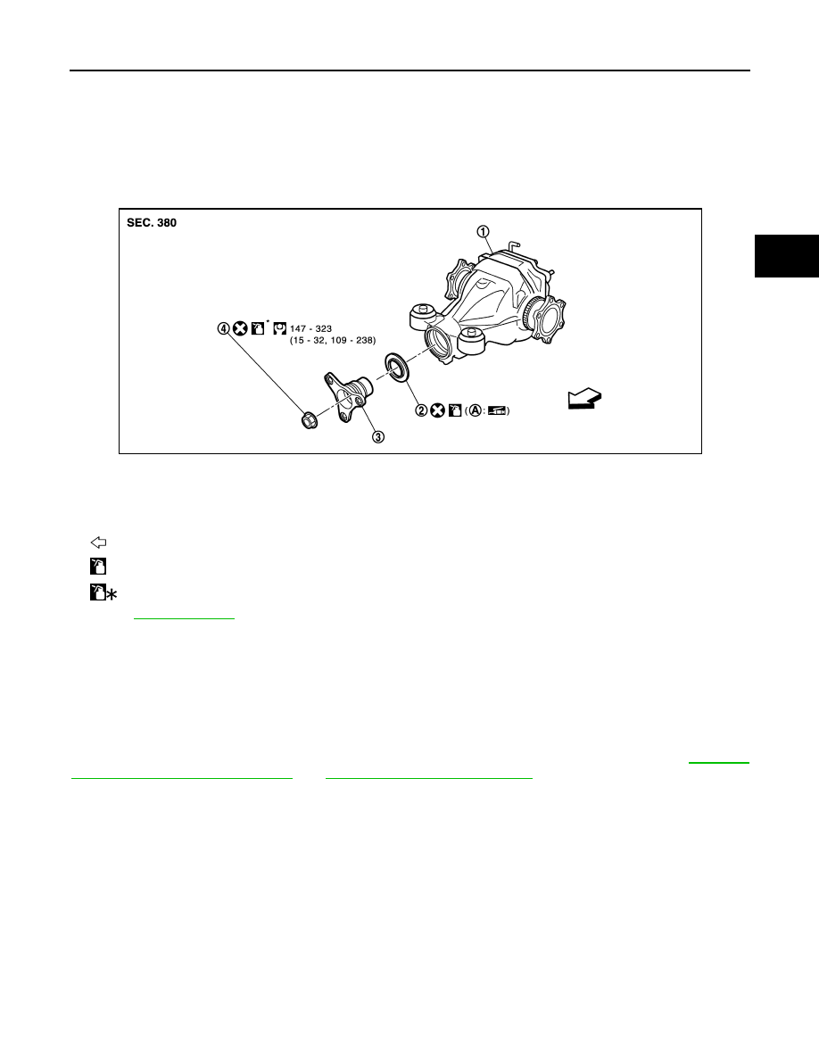
Identification stamp of replacement frequency of front oil seal
1.
Final drive assembly
2.
Front oil seal
3.
Companion flange
4.
Drive pinion lock nut
A.
Oil seal lip
: Vehicle front
: Apply gear oil.
: Apply anti-corrosion oil.
Refer to
for symbols not described above.
JPDID0230GB
DLN-194
< REMOVAL AND INSTALLATION >
[REAR FINAL DRIVE: R200]
FRONT OIL SEAL
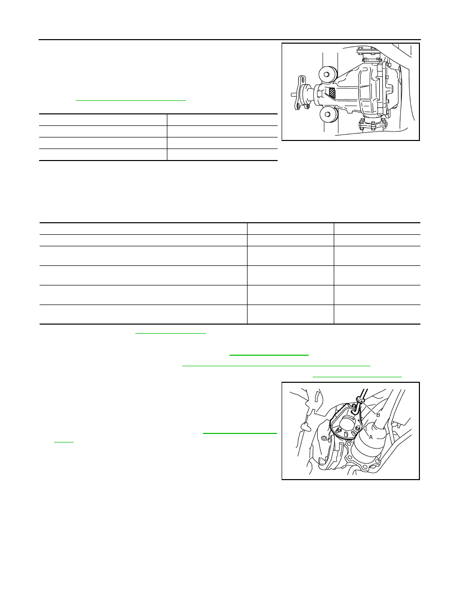
• The diagonally shaded area in the figure shows stamping point for
replacement frequency of front oil seal.
• The following table shows if collapsible spacer replacement is
needed before replacing front oil seal.
When collapsible spacer replacement is required, disassemble
final drive assembly to replace collapsible spacer and front oil seal.
Refer to
CAUTION:
Make a stamping after replacing front oil seal.
• After replacing front oil seal, make a stamping on the stamping point in accordance with the table below in
order to identify replacement frequency.
CAUTION:
Make a stamping from left to right.
1.
Drain gear oil. Refer to
.
2.
Make a judgment if a collapsible spacer replacement is required.
3.
Remove center muffler with a power tool. Refer to
4.
Remove rear wheel sensor. Refer to
BRC-132, "REAR WHEEL SENSOR : Exploded View"
.
5.
Remove drive shaft from final drive. Then suspend it by wire, etc. Refer to
6.
Install attachment (A) [SST: KV40104100 (
—
)] to side
flange, and then pull out the side flange with the sliding hammer
(B) [SST: ST36230000 (J-25840-A)].
NOTE:
Circular clip installation position: Final drive side
7.
Remove rear propeller shaft. Refer to
.
Stamp
collapsible spacer replacement
No stamp
Not required
“0” or “0” on the far right of stamp
Required
“01” or “1” on the far right of stamp
Not required
JSDIA0104ZZ
Stamp before stamping
Stamping on the far right
Stamping
No stamp
0
0
“0”
(Front oil seal was replaced once.)
1
01
“01”
(Collapsible spacer and front oil seal were replaced last time.)
0
010
“0” is on the far right.
(Only front oil seal was replaced last time.)
1
...01
“1” is on the far right.
(Collapsible spacer and front oil seal were replaced last time.)
0
...010
JSDIA0105ZZ
Нет комментариевНе стесняйтесь поделиться с нами вашим ценным мнением.
Текст