Infiniti FX35, FX50 (S51). Manual — part 186
AV
RGB (B: BLUE) SIGNAL CIRCUIT (VIDEO DISTRIBUTOR TO REAR DISPLAY
UNIT)
AV-517
< DTC/CIRCUIT DIAGNOSIS >
[NAVIGATION (TWIN MONITOR)]
C
D
E
F
G
H
I
J
K
L
M
B
A
O
P
RGB (B: BLUE) SIGNAL CIRCUIT (VIDEO DISTRIBUTOR TO REAR DIS-
PLAY UNIT)
Description
INFOID:0000000005247318
Transmit the image displayed with video distributor with RGB signal to the rear display unit.
Diagnosis Procedure
INFOID:0000000005247319
1.
CHECK CONTINUITY RGB (B: BLUE) SIGNAL CIRCUIT
1.
Turn ignition switch OFF.
2.
Disconnect rear display unit connector and video distributor connector.
3.
Check continuity between rear display unit harness connector and video distributor harness connector.
4.
Check continuity between rear display unit harness connector and ground.
Is the inspection result normal?
YES
>> GO TO 2.
NO
>> Repair harness or connector.
2.
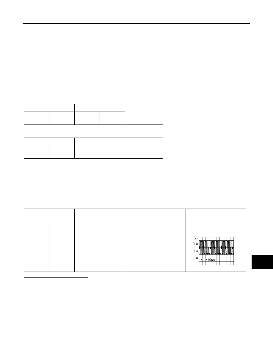
CHECK RGB (B: BLUE) SIGNAL
1.
Connect rear display unit connector and video distributor connector.
2.
Turn ignition switch ON.
3.
Check signal between rear display unit harness connector and ground using an oscilloscope.
Is the inspection result normal?
YES
>> Replace rear display unit.
NO
>> Replace video distributor.
Rear display unit
Video distributor
Continuity
Connector
Terminal
Connector
Terminal
B26
20
M97
28
Existed
Rear display unit
Ground
Continuity
Connector
Terminal
B26
20
Not existed
(+)
(
−
)
Condition
Reference value
Rear display unit
Connector
Terminal
B26
20
Ground
Rear seat remote controller opera-
tion when AUX or DVD image is
displayed on rear display unit.
JSNIA1031ZZ
AV-518
< DTC/CIRCUIT DIAGNOSIS >
[NAVIGATION (TWIN MONITOR)]
RGB AREA (YS) SIGNAL CIRCUIT (VIDEO DISTRIBUTOR TO REAR DISPLAY
UNIT)
RGB AREA (YS) SIGNAL CIRCUIT (VIDEO DISTRIBUTOR TO REAR DIS-
PLAY UNIT)
Description
INFOID:0000000005247320
Transmits the display area of RGB image displayed by video distributor with RGB area (YS) signal to rear dis-
play unit.
Diagnosis Procedure
INFOID:0000000005247321
1.
CHECK CONTINUITY RGB AREA (YS) SIGNAL CIRCUIT
1.
Turn ignition switch OFF.
2.
Disconnect rear display unit connector and video distributor connector.
3.
Check continuity between rear display unit harness connector and video distributor harness connector.
4.
Check continuity between rear display unit harness connector and ground.
Is the inspection result normal?
YES
>> GO TO 2.
NO
>> Repair harness or connector.
2.
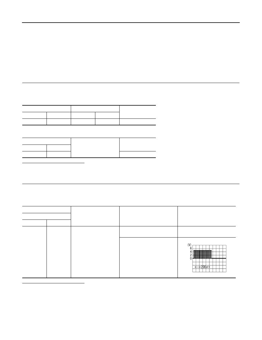
CHECK RGB AREA (YS) SIGNAL
1.
Connect rear display unit connector and video distributor connector.
2.
Turn ignition switch ON.
3.
Check signal between rear display unit harness connector and ground using an oscilloscope.
Is the inspection result normal?
YES
>> Replace rear display unit.
NO
>> Replace video distributor.
Rear display unit
Video distributor
Continuity
Connector
Terminal
Connector
Terminal
B26
15
M97
32
Existed
Rear display unit
Ground
Continuity
Connector
Terminal
B26
15
Not existed
(+)
(
−
)
Condition
Reference value
Rear display unit
Connector
Terminal
B26
15
Ground
When AUX or DVD image is dis-
played on rear display unit.
0 V
Rear seat remote controller opera-
tion when AUX or DVD image is
displayed on rear display unit.
PKIB4948J
AV
VERTICAL SYNCHRONIZING SIGNAL CIRCUIT (REAR DISPLAY UNIT TO VID-
EO DISTRIBUTOR)
AV-519
< DTC/CIRCUIT DIAGNOSIS >
[NAVIGATION (TWIN MONITOR)]
C
D
E
F
G
H
I
J
K
L
M
B
A
O
P
VERTICAL SYNCHRONIZING SIGNAL CIRCUIT (REAR DISPLAY UNIT TO
VIDEO DISTRIBUTOR)
Description
INFOID:0000000005247322
In composite image (DVD and AUX images), transmit the vertical synchronizing (VP) signal and horizontal
synchronizing (HP) signal from rear display unit to video distributor so as to synchronize the RGB images dis-
played with video distributor such as the image quality adjusting menu, etc.
Diagnosis Procedure
INFOID:0000000005247323
1.
CHECK CONTINUITY VERTICAL SYNCHRONIZING (VP) SIGNAL CIRCUIT
1.
Turn ignition switch OFF.
2.
Disconnect rear display unit connector and video distributor connector.
3.
Check continuity between rear display unit harness connector and video distributor harness connector.
4.
Check continuity between rear display unit harness connector and ground.
Is the inspection result normal?
YES
>> GO TO 2.
NO
>> Repair harness or connector.
2.
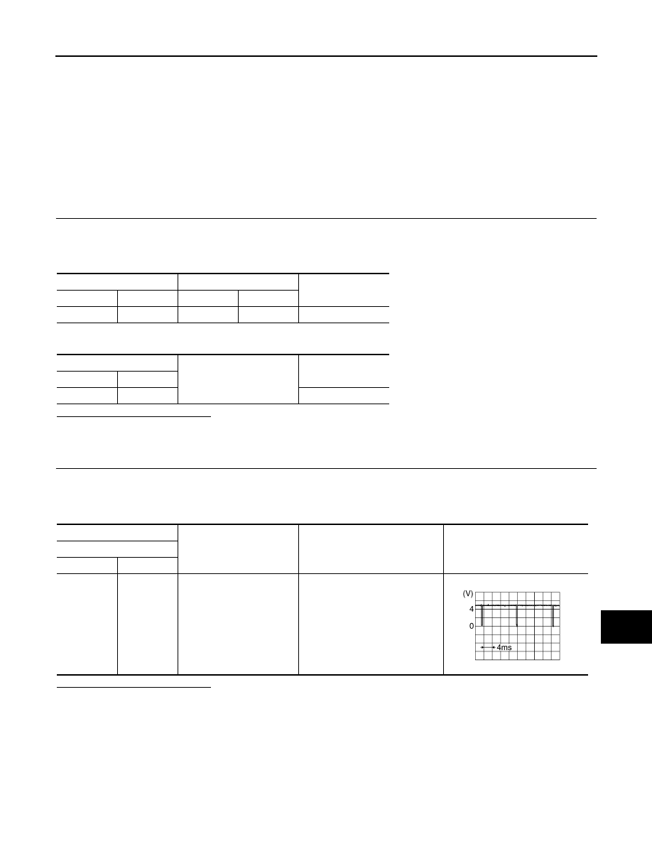
CHECK VERTICAL SYNCHRONIZING (VP) SIGNAL
1.
Connect rear display unit connector and video distributor connector.
2.
Turn ignition switch ON.
3.
Check signal between rear display unit harness connector and ground using an oscilloscope.
Is the inspection result normal?
YES
>> Replace video distributor.
NO
>> Replace rear display unit.
Rear display unit
Video distributor
Continuity
Connector
Terminal
Connector
Terminal
B26
17
M97
29
Existed
Rear display unit
Ground
Continuity
Connector
Terminal
B26
17
Not existed
(+)
(
−
)
Condition
Reference value
Rear display unit
Connector
Terminal
B26
17
Ground
—
SKIB3598E
AV-520
< DTC/CIRCUIT DIAGNOSIS >
[NAVIGATION (TWIN MONITOR)]
HORIZONTAL SYNCHRONIZING SIGNAL CIRCUIT (REAR DISPLAY UNIT TO
VIDEO DISTRIBUTOR)
HORIZONTAL SYNCHRONIZING SIGNAL CIRCUIT (REAR DISPLAY UNIT
TO VIDEO DISTRIBUTOR)
Description
INFOID:0000000005247324
In composite image (DVD and AUX images), transmit the vertical synchronizing (VP) signal and horizontal
synchronizing (HP) signal from rear display unit to video distributor so as to synchronize the RGB images dis-
played with video distributor such as the image quality adjusting menu, etc.
Diagnosis Procedure
INFOID:0000000005247325
1.
CHECK CONTINUITY HORIZONTAL SYNCHRONIZING (HP) SIGNAL CIRCUIT
1.
Turn ignition switch OFF.
2.
Disconnect rear display unit connector and video distributor connector.
3.
Check continuity between rear display unit harness connector and video distributor harness connector.
4.
Check continuity between rear display unit harness connector and ground.
Is the inspection result normal?
YES
>> GO TO 2.
NO
>> Repair harness or connector.
2.
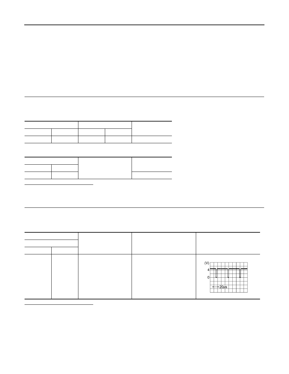
CHECK HORIZONTAL SYNCHRONIZING (HP) SIGNAL
1.
Connect rear display unit connector and video distributor connector.
2.
Turn ignition switch ON.
3.
Check signal between rear display unit harness connector and ground using an oscilloscope.
Is the inspection result normal?
YES
>> Replace video distributor.
NO
>> Replace rear display unit.
Rear display unit
Video distributor
Continuity
Connector
Terminal
Connector
Terminal
B26
18
M97
30
Existed
Rear display unit
Ground
Continuity
Connector
Terminal
B26
18
Not existed
(+)
(
−
)
Condition
Reference value
Rear display unit
Connector
Terminal
B26
18
Ground
—
SKIB3601E
Нет комментариевНе стесняйтесь поделиться с нами вашим ценным мнением.
Текст