Infiniti FX35, FX50 (S51). Manual — part 970
EM-180
< REMOVAL AND INSTALLATION >
[VK50VE]
INTAKE MANIFOLD
Removal and Installation
INFOID:0000000005245227
REMOVAL
WARNING:
To avoid the danger of being scalded, never drain the engine coolant when the engine is hot.
1.
Remove engine cover and engine room cover (RH and LH). Refer to
2.
Release fuel pressure. Refer to
.
3.
Remove air duct (inlet) and air duct. Refer to
4.
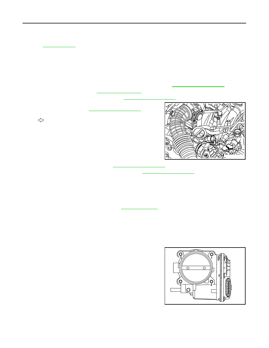
Remove quick connector cap (1) and disconnect fuel feed hose
(2) on engine side. Refer to
.
5.
Remove engine cover bracket. Refer to
6.
Remove fuel injector and fuel tube assembly. Refer to
.
7.
Disconnect manifold absolute pressure (MAP) sensor and air fuel ratio sensor 1 (bank 1) harness connec-
tor.
8.
Remove vacuum tank, EVAP service port hose and EVAP canister purge control solenoid valve.
9.
Disconnect PCV hoses and vacuum hose from intake manifold.
• Add matching marks as necessary for easier installation.
10. Drain engine coolant from radiator. Refer to
.
CAUTION:
• Perform this step when the engine is cold.
• Never spill engine coolant on drive belts.
NOTE:
When removing only intake manifold, move electric throttle control actuator without disconnecting the
water hoses.
11. Remove electric throttle control actuator.
• Loosen mounting bolts in reverse order as shown in the figure.
NOTE:
• The figure shows the electric throttle control actuator (bank 1)
viewed from the air duct side.
• Viewed from the air duct side, the order of loosening mounting
bolts of electric throttle control actuator (bank 1) is the same
as that of the electric throttle control actuator (bank 2).
CAUTION:
• Handle carefully to avoid any impact to electric throttle
control actuator.
• Never disassemble.
12. Remove intake manifold with power tool.
A.
To centralized under-floor piping
B.
To rocker cover (bank 2)
C.
To water inlet
D.
Front mark
E.
To cylinder head
F.
To rocker cover (bank 1)
G.
To brake booster
Refer to
for symbols in the figure.
: Engine front
JPBIA2076ZZ
JPBIA2362ZZ
INTAKE MANIFOLD
EM-181
< REMOVAL AND INSTALLATION >
[VK50VE]
C
D
E
F
G
H
I
J
K
L
M
A
EM
N
P
O
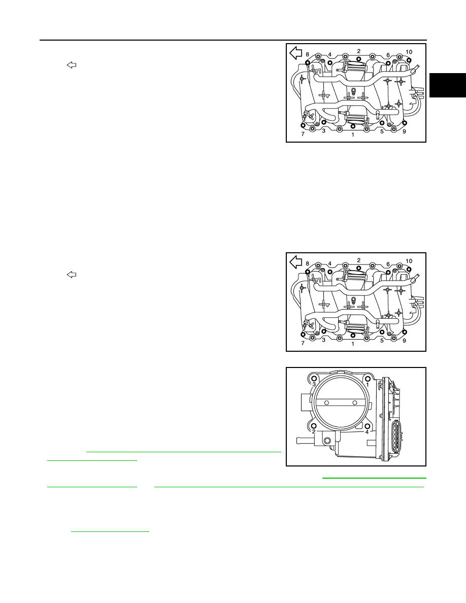
• Loosen mounting bolts in reverse order as shown in the figure.
13. Remove intake manifold gaskets.
CAUTION:
Cover engine openings to avoid entry of foreign materials.
14. Remove manifold absolute pressure (MAP) sensor, if necessary.
CAUTION:
Handle carefully to avoid any impact to manifold absolute pressure (MAP) sensor.
15. Remove acoustic absorbent.
INSTALLATION
Note the following item, and install in the reverse order of removal.
Intake Manifold
Tighten in numerical order as shown in the figure.
Electric Throttle Control Actuator
• Tighten in numerical order as shown in the figure.
NOTE:
• The figure shows the electric throttle control actuator (bank 1)
viewed from the air duct side.
• Viewed from the air duct side, the order of tightening mounting
bolts of electric throttle control actuator (bank 1) is the same as
that of the electric throttle control actuator (bank 2).
• Perform the “Throttle Valve Closed Position Learning” when har-
ness connector of electric throttle control actuator is disconnected.
Refer to
EC-581, "THROTTLE VALVE CLOSED POSITION
.
• Perform the “Idle Air Volume Learning” and “Throttle Valve Closed
Position Learning” when electric throttle control actuator is replaced. Refer to
EC-581, "THROTTLE VALVE CLOSED POSITION LEARNING : Description"
.
Water Hose
Insert hose by 27 to 32 mm (1.06 to 1.26 in) from connector end.
Vacuum Hose
: Engine front
JPBIA2077ZZ
: Engine front
JPBIA2077ZZ
JPBIA2362ZZ
EM-182
< REMOVAL AND INSTALLATION >
[VK50VE]
FUEL INJECTOR AND FUEL TUBE
FUEL INJECTOR AND FUEL TUBE
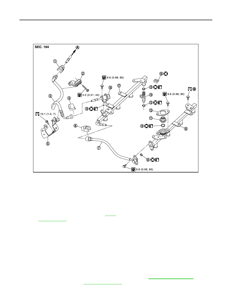
Exploded View
INFOID:0000000005245228
CAUTION:
Never remove or disassemble parts unless instructed as shown in the figure.
Removal and Installation
INFOID:0000000005245229
REMOVAL
WARNING:
• Put a “CAUTION: FLAMMABLE” sign in the workshop.
• Be sure to work in a well ventilated area and furnish workshop with a CO
2
fire extinguisher.
• Never smoke while servicing fuel system. Keep open flames and sparks away from the work area.
• To avoid the danger of being scalded, never drain engine coolant when engine is hot.
1.
Remove engine cover and engine room cover (RH and LH). Refer to
2.
Release fuel pressure. Refer to
.
1.
Quick connector cap
2.
Fuel hose bracket
3.
Fuel feed hose
4.
Quick connector cap
5.
Fuel hose bracket
6.
Quick connector cap
7.
Fuel hose (center)
8.
O-ring
9.
Fuel tube (bank 1)
10. O-ring
11. Fuel damper
12. Fuel damper cap
13. O-ring (green)
14. Fuel injector
15. O-ring (black)
16. Clip
17. Fuel tube (bank 2)
18. Fuel feed damper
19. O-ring
A.
To centralized under-floor piping
B.
Refer to
Refer to
for symbols in the figure.
JPBIA2081GB
FUEL INJECTOR AND FUEL TUBE
EM-183
< REMOVAL AND INSTALLATION >
[VK50VE]
C
D
E
F
G
H
I
J
K
L
M
A
EM
N
P
O
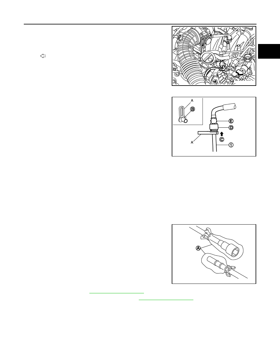
3.
Remove the fuel feed hose (2) on the fuel feed damper side with
quick connector release (commercial service tool: J-45488) as
per the followings steps.
CAUTION:
Use the quick connector release for removing the fuel feed
hose on the centralized under-floor piping side as well as
the fuel feed damper side although the shape of the quick
connector is different.
a.
Remove quick connector cap from quick connector connection.
b.
With the sleeve side (B) of quick connector release (A) facing to
quick connector (D), install quick connector release onto fuel
feed hose.
c.
Insert quick connector release into quick connector until sleeve
contacts and goes no further. Hold quick connector release on
that position.
CAUTION:
Inserting quick connector release hard will not disconnect
quick connector. Hold quick connector release where it contacts and goes no further.
d.
Pull out quick connector straight from fuel feed damper.
CAUTION:
• Pull quick connector holding position (E) as shown in the figure.
• Never pull with lateral force applied. O-ring inside quick connector may be damaged.
• Prepare container and cloth beforehand as fuel will leak out.
• Avoid fire and sparks.
• Keep parts away from heat source. Especially, be careful when welding is performed around
them.
• Never expose parts to battery electrolyte or other acids.
• Never bend or twist connection between quick connector and fuel feed hose during installation/
removal.
• To keep the connecting portion clean and to avoid dam-
age and foreign materials, cover them completely with
plastic bags (A) or something similar.
4.
Remove air duct. Refer to
5.
Remove electric throttle control actuator. Refer to
6.
Remove fuel hose (center).
• The procedure for removing the quick connector is the same as for removing the fuel feed damper.
CAUTION:
Disconnect quick connector by using quick connector release (commercial service tool: J-45488),
not by picking out retainer tabs.
7.
Remove fuel tube and fuel injector assembly.
1.
: Quick connector cap
: Engine front
1
: Fuel feed damper
C
: Insert and retain
JPBIA2076ZZ
JPBIA2083ZZ
JPBIA2084ZZ
Нет комментариевНе стесняйтесь поделиться с нами вашим ценным мнением.
Текст