Infiniti FX35, FX50 (S51). Manual — part 969
EM-176
< REMOVAL AND INSTALLATION >
[VK50VE]
DRIVE BELT AUTO TENSIONER AND IDLER PULLEY
DRIVE BELT AUTO TENSIONER AND IDLER PULLEY
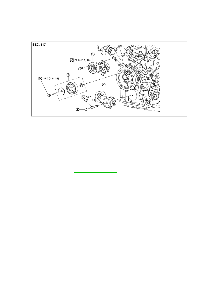
Exploded View
INFOID:0000000005245221
Removal and Installation
INFOID:0000000005245222
Removal
CAUTION:
The complete drive belt auto-tensioner must be replaced as a unit, including the pulley.
1.
Remove drive belts. Refer to
• Keep auto-tensioner pulley arm locked after drive belt is removed.
2.
Remove drive belt auto-tensioners.
• Keep auto-tensioner pulley arm locked to install or remove auto-tensioner.
CAUTION:
Never loosen the hexagonal part in center of drive belt auto tensioner pulley (Never turn it clock-
wise). If turned clockwise, the complete drive belt auto tensioner must be replaced as a unit,
including the pulley.
3.
Remove idler pulley.
Installation
Installation is the reverse order of removal.
CAUTION:
Never swap the pulley between new and old drive belt auto tensioner.
1.
Auto-tensioner (for alternator, water pump
and A/C compressor belt)
2.
Idler pulley
3.
Cover
4.
Auto-tensioner (for power steering oil pump
belt)
Refer to
for symbols in the figure.
JPBIA2073GB
AIR CLEANER AND AIR DUCT
EM-177
< REMOVAL AND INSTALLATION >
[VK50VE]
C
D
E
F
G
H
I
J
K
L
M
A
EM
N
P
O
AIR CLEANER AND AIR DUCT
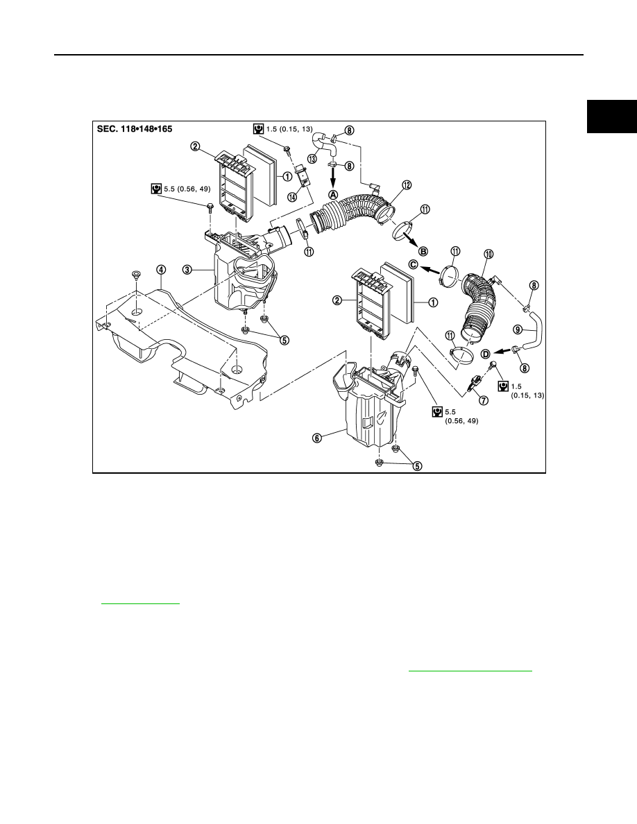
Exploded View
INFOID:0000000005245223
Removal and Installation
INFOID:0000000005245224
REMOVAL
1.
Remove engine cover and engine room cover (RH and LH). Refer to
.
2.
Remove air duct (inlet).
3.
Disconnect mass air flow sensor harness connector.
4.
Disconnect PCV hose.
5.
Remove air cleaner case & mass air flow sensor assembly and air duct by disconnecting their joints.
• Add matching marks, if necessary for easier installation.
6.
Remove mass air flow sensor from air cleaner case, if necessary.
CAUTION:
Handle mass air flow sensor according to the following instructions.
1.
Air cleaner filter
2.
Holder
3.
Air cleaner case (bank 2)
4.
Air duct (inlet)
5.
Grommet
6.
Air cleaner case (bank 1)
7.
Mass air flow sensor (bank 1)
8.
Clamp
9.
PCV hose
10. Air duct (bank 1)
11.
Clamp
12. Air duct (bank 2)
13. PCV hose
14. Mass air flow sensor (bank 2)
A.
To rocker cover (bank 2)
B.
To electric throttle control actuator
(bank 2)
C.
To electric throttle control actuator
(bank 1)
D.
To rocker cover (bank 1)
Refer to
for symbols in the figure.
JPBIA2063GB

EM-178
< REMOVAL AND INSTALLATION >
[VK50VE]
AIR CLEANER AND AIR DUCT
• Never impact mass air flow sensor.
• Never disassemble mass air flow sensor.
• Never touch mass air flow sensor.
INSTALLATION
Note the following item, and install in the reverse order of removal.
• Align marks. Attach each joint. Screw clamps firmly.
Inspection
INFOID:0000000005245225
INSPECTION AFTER REMOVAL
Inspect air duct assembly for crack or tear.
• If damage is found, replace air duct assembly
Clamp tightening torque
:4.5 N·m (0.46 kg-m, 40 in-lb)
INTAKE MANIFOLD
EM-179
< REMOVAL AND INSTALLATION >
[VK50VE]
C
D
E
F
G
H
I
J
K
L
M
A
EM
N
P
O
INTAKE MANIFOLD
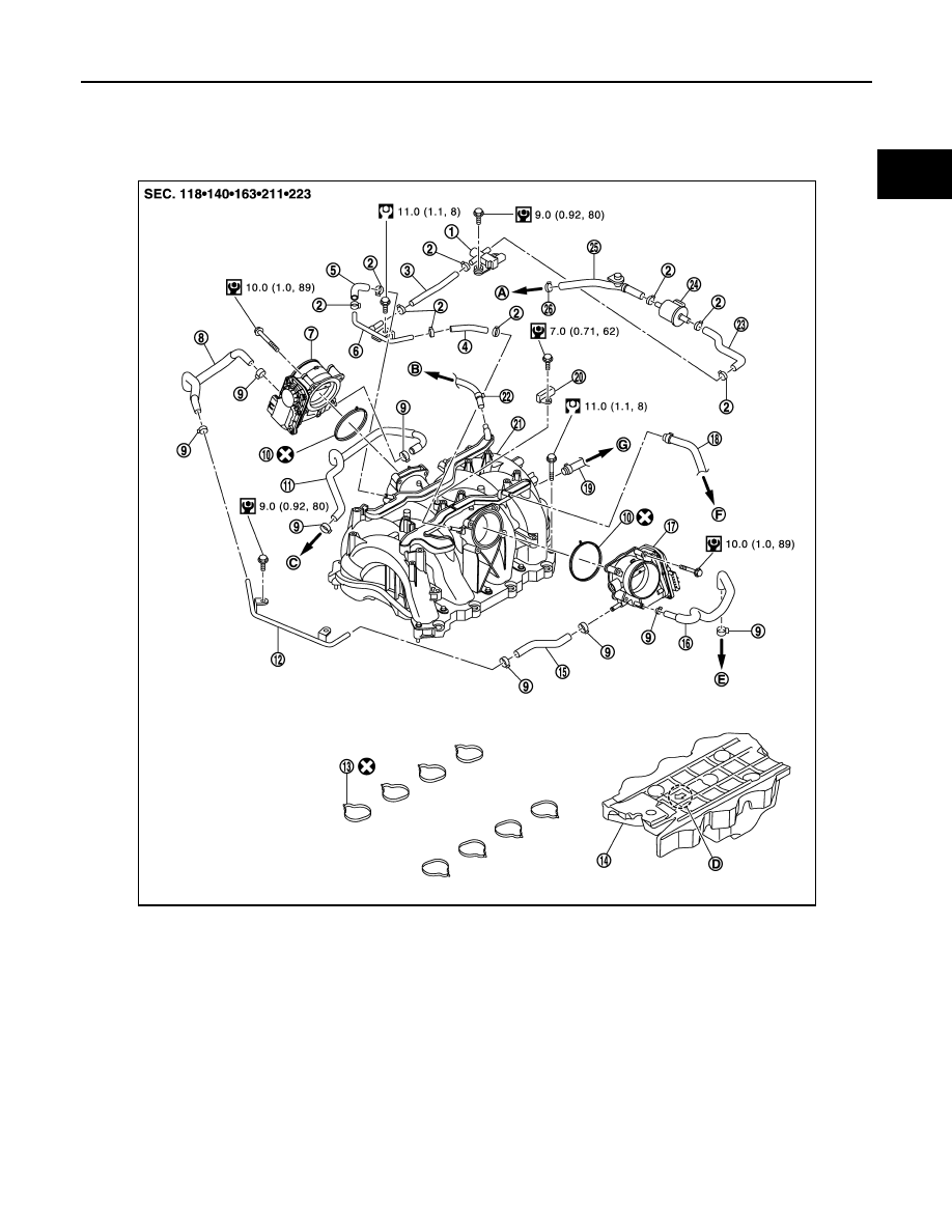
Exploded View
INFOID:0000000005245226
1.
EVAP canister purge control sole-
noid valve
2.
Clamp
3.
EVAP hose
4.
EVAP hose
5.
EVAP hose
6.
EVAP tube
7.
Electric throttle control actuator
(bank 2)
8.
Water hose
9.
Clamp
10.
Gasket
11.
Water hose
12.
Water pipe
13.
Gasket
14.
Acoustic absorbent
15.
Water hose
16.
Water hose
17.
Electric throttle control actuator
(bank 1)
18.
PCV hose
19.
Vacuum hose
20.
Manifold absolute pressure (MAP)
sensor
21.
Intake manifold
22.
PCV hose
23.
EVAP hose
24.
Vacuum tank
25.
EVAP service port hose
26.
Clamp
JPBIA2075GB
Нет комментариевНе стесняйтесь поделиться с нами вашим ценным мнением.
Текст