Infiniti FX35, FX50 (S51). Manual — part 968
EM-172
< PERIODIC MAINTENANCE >
[VK50VE]
CAMSHAFT VALVE CLEARANCE
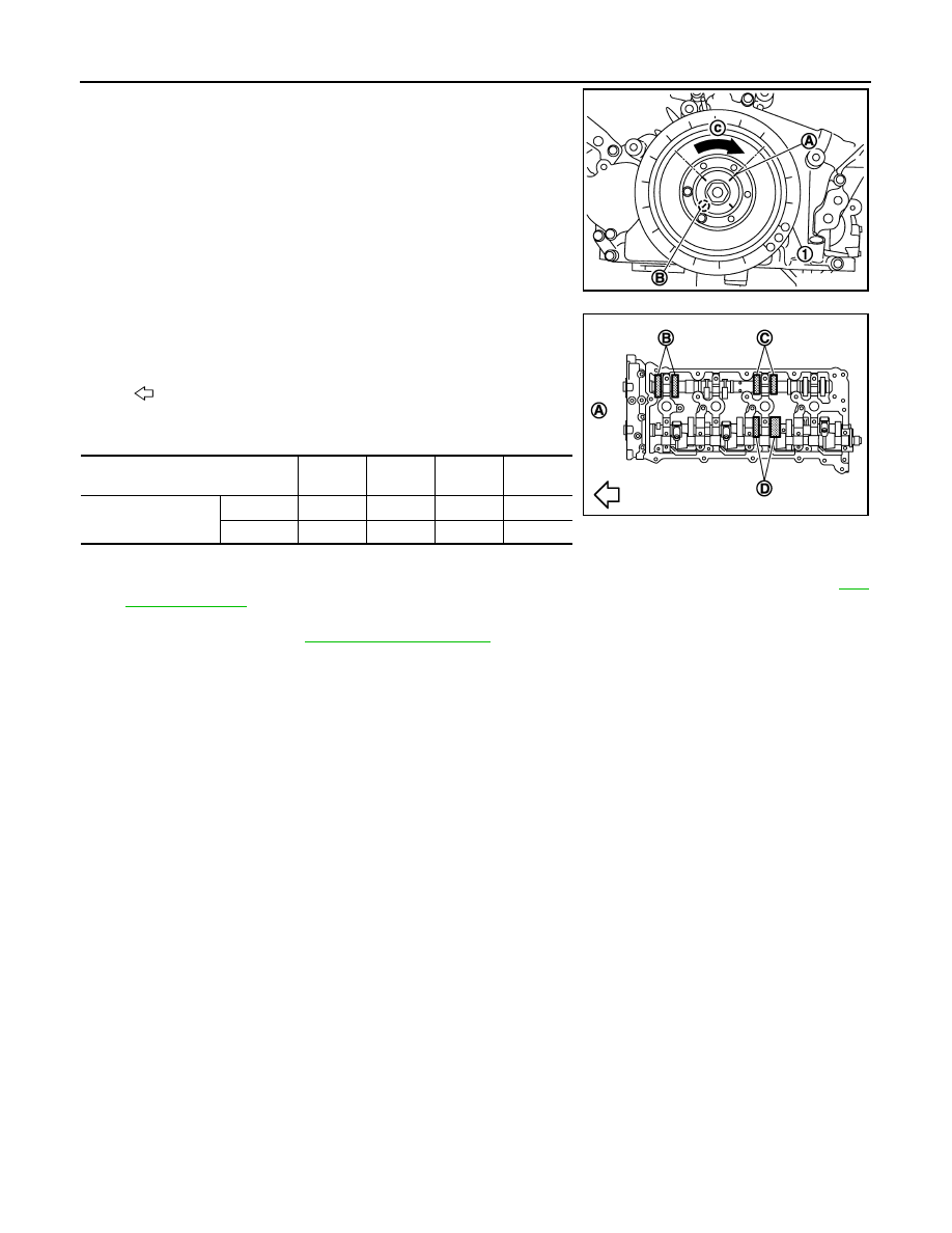
Crankshaft pulley mounting bolt flange has an angle mark (B)
every 90 degrees (c). They can be used as a guide to rotation
angle.
• By referring to the figure, measure the valve clearances at
locations marked “
×
” as shown in the table below (locations
indicated in the figure).
• No. 6 cylinder at compression TDC
3.
Perform adjustment or replacement if the measured value is out of the standard.
• If a valve clearance on the exhaust side is out of specification, adjust the valve clearance. Refer to
.
• If a valve clearance on the intake side is out of specification, replace VVEL ladder assembly & cylinder
head assembly. Refer to
CAUTION:
Never adjust valve clearance on the intake side.
NOTE:
Since the valve lifter (INT) cannot be replaced by the piece, VVEL ladder assembly & cylinder head
assembly replacement are required.
A
: Paint mark
JPBIA2066ZZ
: Engine front
Measuring position [bank 2 (A)]
No. 2
CYL.
No. 4
CYL.
No. 6
CYL.
No. 8
CYL.
No. 6 cylinder at com-
pression TDC
EXH
×
(B)
×
(C)
INT
×
(D)
JPBIA2069ZZ
COMPRESSION PRESSURE
EM-173
< PERIODIC MAINTENANCE >
[VK50VE]
C
D
E
F
G
H
I
J
K
L
M
A
EM
N
P
O
COMPRESSION PRESSURE
Inspection
INFOID:0000000005245218
1.
Warm up engine thoroughly. Then, stop it.
2.
Release fuel pressure. Refer to
.
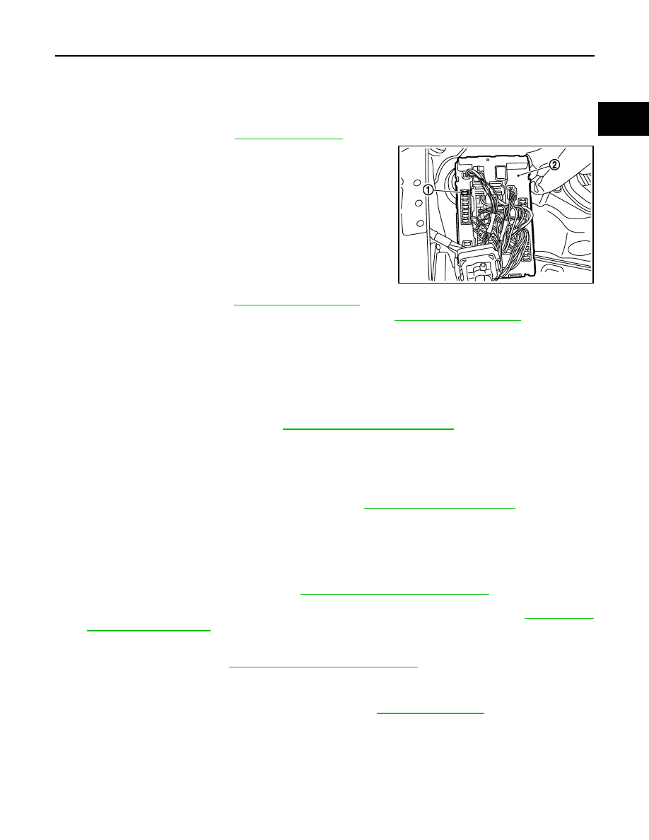
3.
Disconnect fuel pump fuse (1) from IPDM E/R (2) to avoid fuel
injection during measurement.
4.
Remove engine cover. Refer to
.
5.
Remove ignition coil and spark plug from each cylinder. Refer to
6.
Connect engine tachometer (not required in use of CONSULT-III).
7.
Measure compression pressure using compression gauge connected with flexible type adapter (commer-
cial service tool).
8.
With accelerator pedal fully depressed, turn ignition switch to “START” for cranking. When the gauge
pointer stabilizes, read the compression pressure and the engine rpm. Perform these steps to check each
cylinder.
CAUTION:
• Measure a six-cylinder under the same conditions since a measurement depends on measure-
ment conditions (engine water temperature, etc.).
• Always use a fully charged battery to obtain the specified engine speed.
• If the engine speed is out of the specified range, check battery liquid for proper gravity. Check the
engine speed again with normal battery gravity. Refer to
• If compression pressure is below the minimum value, check valve clearances and parts associated with
combustion chamber (valve, valve seat, piston, piston ring, cylinder bore, cylinder head, and cylinder
head gasket). After checking, measure compression pressure again.
• If a cylinder has low compression pressure, pour a small amount of engine oil into the spark plug hole of
the cylinder to recheck it for compression.
- If the added engine oil improves the compression, piston rings may be worn out or damaged. Check pis-
ton rings and replace if necessary. Refer to
EM-256, "Disassembly and Assembly"
.
- If the compression pressure remains at low level despite the addition of engine oil, valves may be mal-
functioning. Check valves for damage. Replace valve or valve seat accordingly. Refer to
• If two adjacent cylinders have respectively low compression pressure and their compression remains
low even after the addition of engine oil, cylinder head gaskets are leaking. In such a case, replace cyl-
inder head gaskets. Refer to
EM-246, "Disassembly and Assembly"
9.
After inspection is completed, install removed parts.
10. Start the engine, and check that the engine runs smoothly.
11. Perform trouble diagnosis. If DTC appears, erase it. Refer to
JMBIA1552ZZ
Compression pressure
: Refer to
EM-174
< REMOVAL AND INSTALLATION >
[VK50VE]
ENGINE ROOM COVER
REMOVAL AND INSTALLATION
ENGINE ROOM COVER
Exploded View
INFOID:0000000005245219
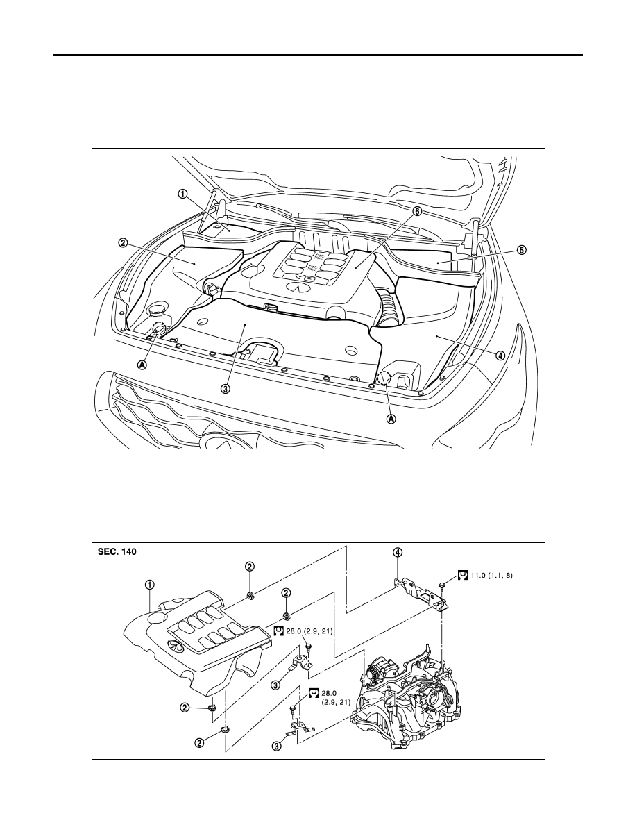
Engine room cover
Engine cover
JPBIA2359ZZ
1.
Battery cover
2.
Engine room cover (RH)
3.
Air duct (inlet)
4.
Engine room cover (LH)
5.
Brake master cylinder cover
6.
Engine cover
A.
Clip
for symbols in the figure.
JPBIA2072GB
ENGINE ROOM COVER
EM-175
< REMOVAL AND INSTALLATION >
[VK50VE]
C
D
E
F
G
H
I
J
K
L
M
A
EM
N
P
O
Removal and Installation
INFOID:0000000005245220
REMOVAL
CAUTION:
Never damage or scratch engine cover when installing or removing.
1.
Remove clip, and remove engine room cover (RH and LH).
2.
Remove engine cover as per the following:
• Front side: Lift and remove fit.
• Rear side: Pull out to forward and remove fit.
3.
Remove battery cover and brake master cylinder cover, if necessary.
4.
Remove air duct (inlet). Refer to
.
INSTALLATION
Installation is the reverse order of removal.
1.
Engine cover
2.
Grommet
3.
Bracket
4.
Bracket (rear)
for symbols in the figure.
Нет комментариевНе стесняйтесь поделиться с нами вашим ценным мнением.
Текст