Infiniti FX35, FX50 (S51). Manual — part 734
ICC BRAKE SWITCH
EC-477
< DTC/CIRCUIT DIAGNOSIS >
[VQ35HR]
C
D
E
F
G
H
I
J
K
L
M
A
EC
N
P
O
Is the inspection result normal?
YES
>> INSPECTION END
NO
>> GO TO 3.
3.
CHECK ICC BRAKE SWITCH POWER SUPPLY CIRCUIT-I
1.
Turn ignition switch OFF.
2.
Disconnect ICC brake switch harness connector.
3.
Turn ignition switch ON.
4.
Check the voltage between ICC brake switch harness connector and ground.
Is the inspection result normal?
YES
>> GO TO 10.
NO
>> GO TO 4.
4.
CHECK ICC BRAKE SWITCH POWER SUPPLY CIRCUIT-II
1.
Turn ignition switch OFF.
2.
Disconnect ICC brake hold relay.
3.
Turn ignition switch ON.
4.
Check the voltage between ICC brake hold relay harness connector and ground.
Is the inspection result normal?
YES
>> GO TO 6.
NO
>> GO TO 5.
5.
DETECT MALFUNCTIONING PART
Check the following.
• Fuse block (J/B) connector E103
• 10 A fuse (No. 3)
• Harness for open or short between ICC brake hold relay and fuse
>> Repair open circuit or short to ground in harness or connectors.
6.
CHECK ICC BRAKE SWITCH POWER SUPPLY CIRCUIT-III
1.
Turn ignition switch OFF.
2.
Check the continuity between ICC brake switch harness connector and ICC brake hold relay harness con-
nector.
3.
Also check harness for short to ground and short to power.
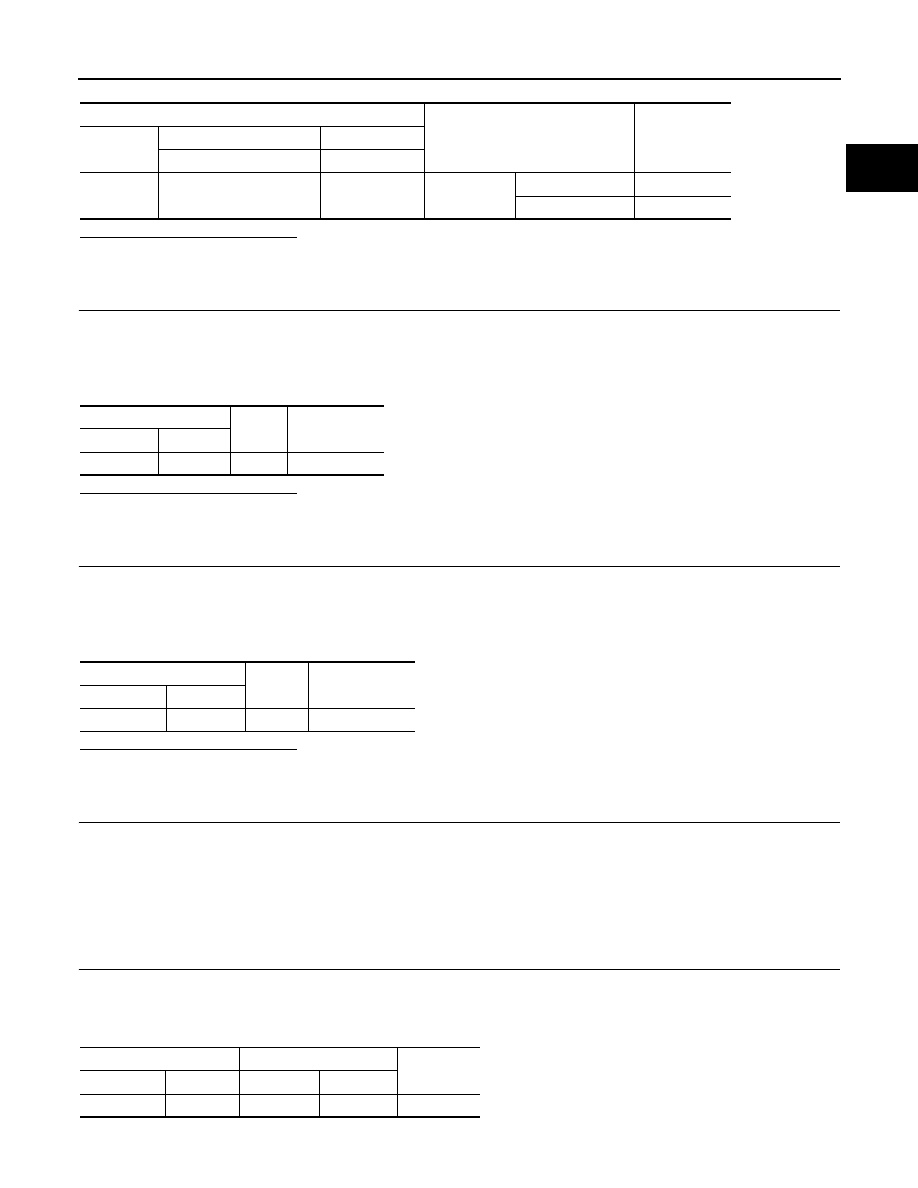
ECM
Condition
Voltage (V)
Connector
+
–
Terminal
Terminal
M107
117
(ICC brake switch signal)
128
Brake pedal
Slightly depressed
Approx. 0
Fully released
Battery voltage
ICC brake switch
Ground
Voltage
Connector
Terminal
E114
1
Ground
Battery voltage
ICC brake hold relay
Ground
Voltage
Connector
Terminal
E91
3
Ground
Battery voltage
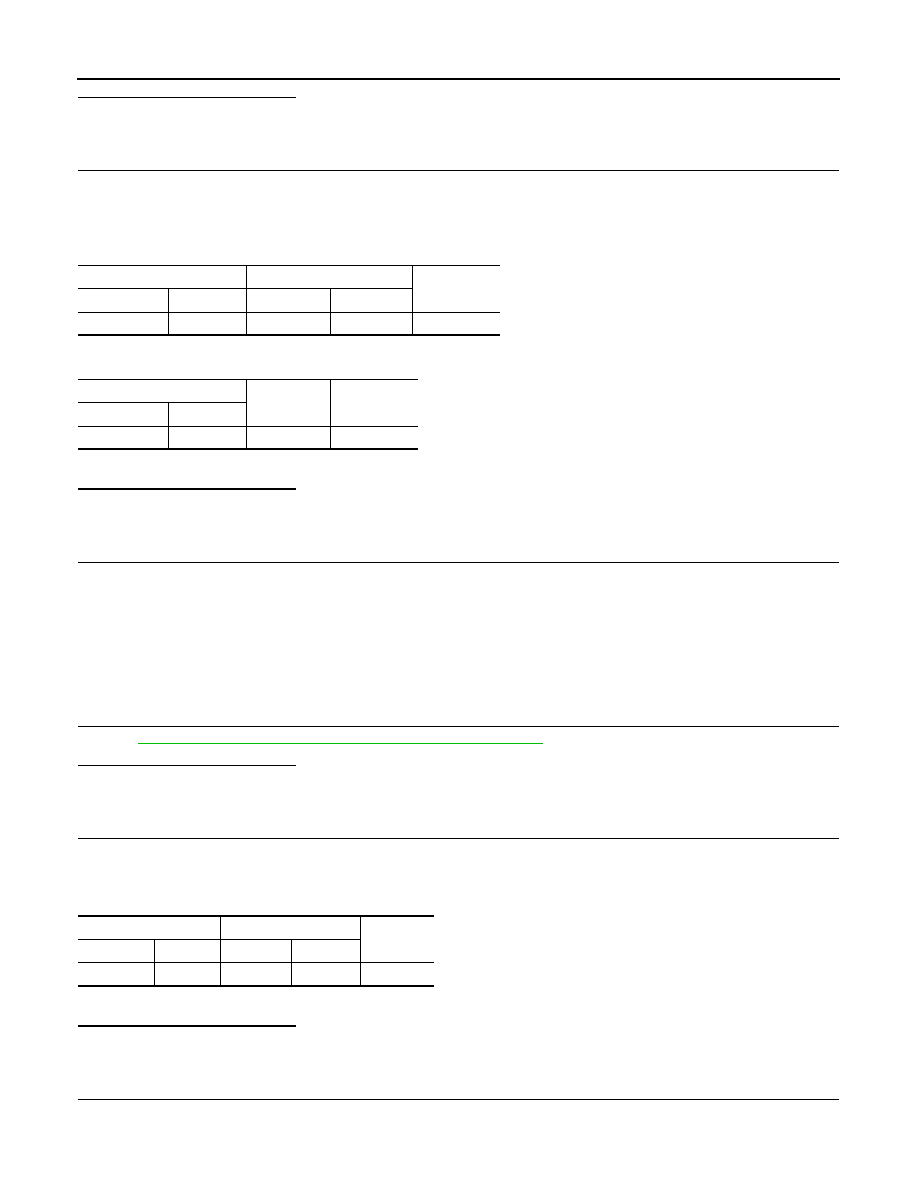
ICC brake switch
ICC brake hold relay
Continuity
Connector
Terminal
Connector
Terminal
E114
1
E91
4
Existed
EC-478
< DTC/CIRCUIT DIAGNOSIS >
[VQ35HR]
ICC BRAKE SWITCH
Is the inspection result normal?
YES
>> GO TO 7.
NO
>> Repair open circuit, short to ground or short to power in harness or connectors.
7.
CHECK ICC BRAKE HOLD RELAY CONTROL CIRCUIT FOR OPEN AND SHORT
1.
Turn ignition switch OFF.
2.
Disconnect brake booster control unit harness connector.
3.
Check the continuity between ICC brake hold relay harness connector and brake booster control unit har-
ness connector.
4.
Check the continuity between ICC brake hold relay harness connector and ground.
5.
Also check harness for short to ground and short to power.
Is the inspection result normal?
YES
>> GO TO 9.
NO
>> GO TO 8.
8.
DETECT MALFUNCTIONING PART
Check the following.
• Harness connectors E106, M6
• Harness connectors M117, B201
• Harness for open or short between ICC brake hold relay and brake booster control unit
• Harness for open or short between ICC brake hold relay and ground
>> Repair open circuit, short to ground or short to power in harness or connectors.
9.
CHECK ICC BRAKE HOLD RELAY
EC-1112, "Component Inspection (ICC Brake Hold Relay)"
.
Is the inspection result normal?
YES
>> GO TO 13.
NO
>> Replace ICC brake hold relay.
10.
CHECK ICC BRAKE SWITCH INPUT SIGNAL CIRCUIT FOR OPEN AND SHORT
1.
Turn ignition switch OFF.
2.
Disconnect ECM harness connector.
3.
Check the continuity between ICC brake switch harness connector and ECM harness connector.
4.
Also check harness for short to ground and short to power.
Is the inspection result normal?
YES
>> GO TO 12.
NO
>> GO TO 11.
11.
DETECT MALFUNCTIONING PART
Check the following.
• Harness connectors E106, M6
ICC brake hold relay
Brake booster control unit
Continuity
Connector
Terminal
Connector
Terminal
E91
1
B249
47
Existed
ICC brake hold relay
Ground
Continuity
Connector
Terminal
E91
2
Ground
Existed
ICC brake switch
ECM
Continuity
Connector
Terminal
Connector
Terminal
E114
2
M107
126
Existed
ICC BRAKE SWITCH
EC-479
< DTC/CIRCUIT DIAGNOSIS >
[VQ35HR]
C
D
E
F
G
H
I
J
K
L
M
A
EC
N
P
O
• Harness for open or short between ICC brake switch and ECM
>> Repair open circuit, short to ground or short to power in harness or connectors.
12.
CHECK ICC BRAKE SWITCH
EC-479, "Component Inspection (ICC Brake Switch)"
.
Is the inspection result normal?
YES
>> GO TO 13.
NO
>> Replace ICC brake switch.
13.
CHECK INTERMITTENT INCIDENT
GI-36, "Intermittent Incident"
.
>> INSPECTION END
Component Inspection (ICC Brake Switch)
INFOID:0000000005237095
1.
CHECK ICC BRAKE SWITCH-I
1.
Turn ignition switch OFF.
2.
Disconnect ICC brake switch harness connector.
3.
Check the continuity between ICC brake switch terminals under the following conditions.
Is the inspection result normal?
YES
>> INSPECTION END
NO
>> GO TO 2.
2.
CHECK ICC BRAKE SWITCH-II
1.
Adjust ICC brake switch installation. Refer to
BR-7, "Inspection and Adjustment"
2.
Check the continuity between ICC brake switch terminals under the following conditions.
Is the inspection result normal?
YES
>> INSPECTION END
NO
>> Replace ICC brake switch.
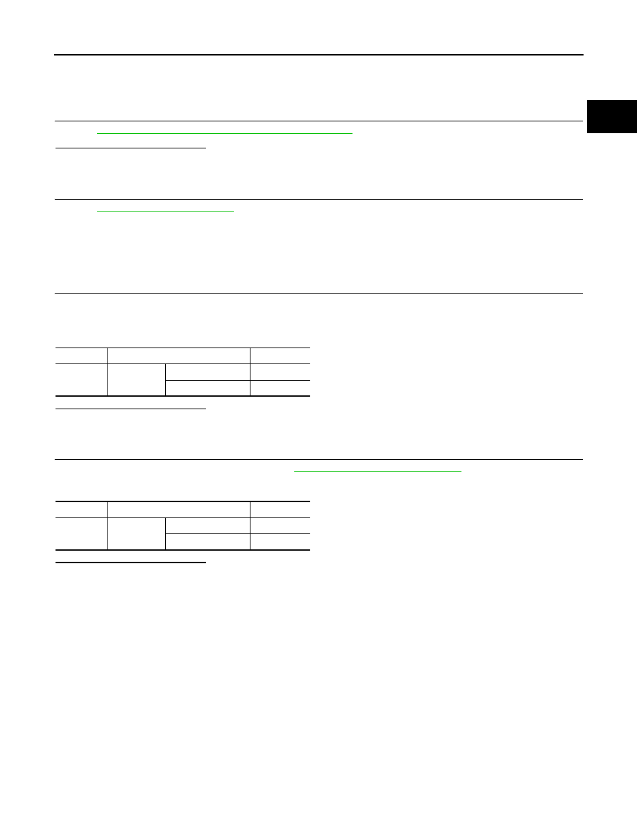
Terminals
Condition
Continuity
1 and 2
Brake pedal
Fully released
Existed
Slightly depressed
Not existed
Terminals
Condition
Continuity
1 and 2
Brake pedal
Fully released
Existed
Slightly depressed
Not existed
EC-480
< DTC/CIRCUIT DIAGNOSIS >
[VQ35HR]
IGNITION SIGNAL
IGNITION SIGNAL
Description
INFOID:0000000005237096
The ignition signal from the ECM is sent to and amplified by the power transistor. The power transistor turns
ON and OFF the ignition coil primary circuit. This ON/OFF operation induces the proper high voltage in the coil
secondary circuit.
Component Function Check
INFOID:0000000005237097
1.
INSPECTION START
Turn ignition switch OFF, and restart engine.
Does the engine start?
YES-1 >> With CONSULT-III: GO TO 2.
YES-2 >> Without CONSULT-III: GO TO 3.
NO
>> Go to
2.
CHECK IGNITION SIGNAL FUNCTION
With CONSULT-III
1.
Perform “POWER BALANCE” in “ACTIVE TEST” mode with CONSULT-III.
2.
Check that each circuit produces a momentary engine speed drop.
Is the inspection result normal?
YES
>> INSPECTION END
NO
>> Go to
3.
CHECK IGNITION SIGNAL FUNCTION
Without CONSULT-III
1.
Let engine idle.
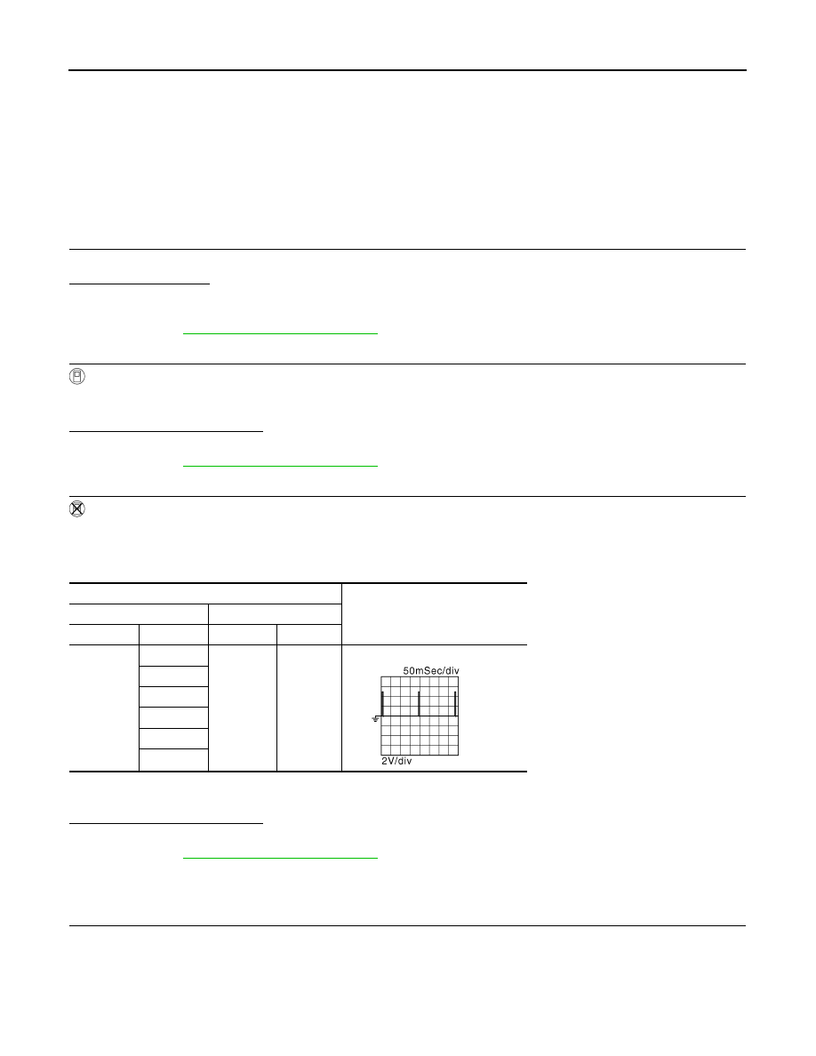
2.
Read the voltage signal between ECM harness connector terminals under the following conditions with an
oscilloscope.
NOTE:
The pulse cycle changes depending on rpm at idle.
Is the inspection result normal?
YES
>> INSPECTION END
NO
>> Go to
Diagnosis Procedure
INFOID:0000000005237098
1.
CHECK IGNITION COIL POWER SUPPLY CIRCUIT-I
1.
Turn ignition switch OFF, wait at least 10 seconds and then turn it ON.
2.
Check the voltage between ECM harness connector terminals under the following conditions.
ECM
Voltage signal
+
–
Connector
Terminal
Connector
Terminal
F101
11
M107
128
12
15
16
19
20
JMBIA0035GB
Нет комментариевНе стесняйтесь поделиться с нами вашим ценным мнением.
Текст