Infiniti FX35, FX50 (S51). Manual — part 733
FUEL PUMP
EC-473
< DTC/CIRCUIT DIAGNOSIS >
[VQ35HR]
C
D
E
F
G
H
I
J
K
L
M
A
EC
N
P
O
FUEL PUMP
Description
INFOID:0000000005237088
*: ECM determines the start signal status by the signals of engine speed and battery voltage.
The ECM activates the fuel pump for several seconds after the ignition switch is turned ON to improve engine
startability. If the ECM receives a engine speed signal from the camshaft position sensor, it knows that the
engine is rotating, and causes the pump to operate. If the engine speed signal is not received when the igni-
tion switch is ON, the engine stalls. The ECM stops pump operation and prevents battery discharging, thereby
improving safety. The ECM does not directly drive the fuel pump. It controls the ON/OFF fuel pump relay,
which in turn controls the fuel pump.
Component Function Check
INFOID:0000000005237089
1.
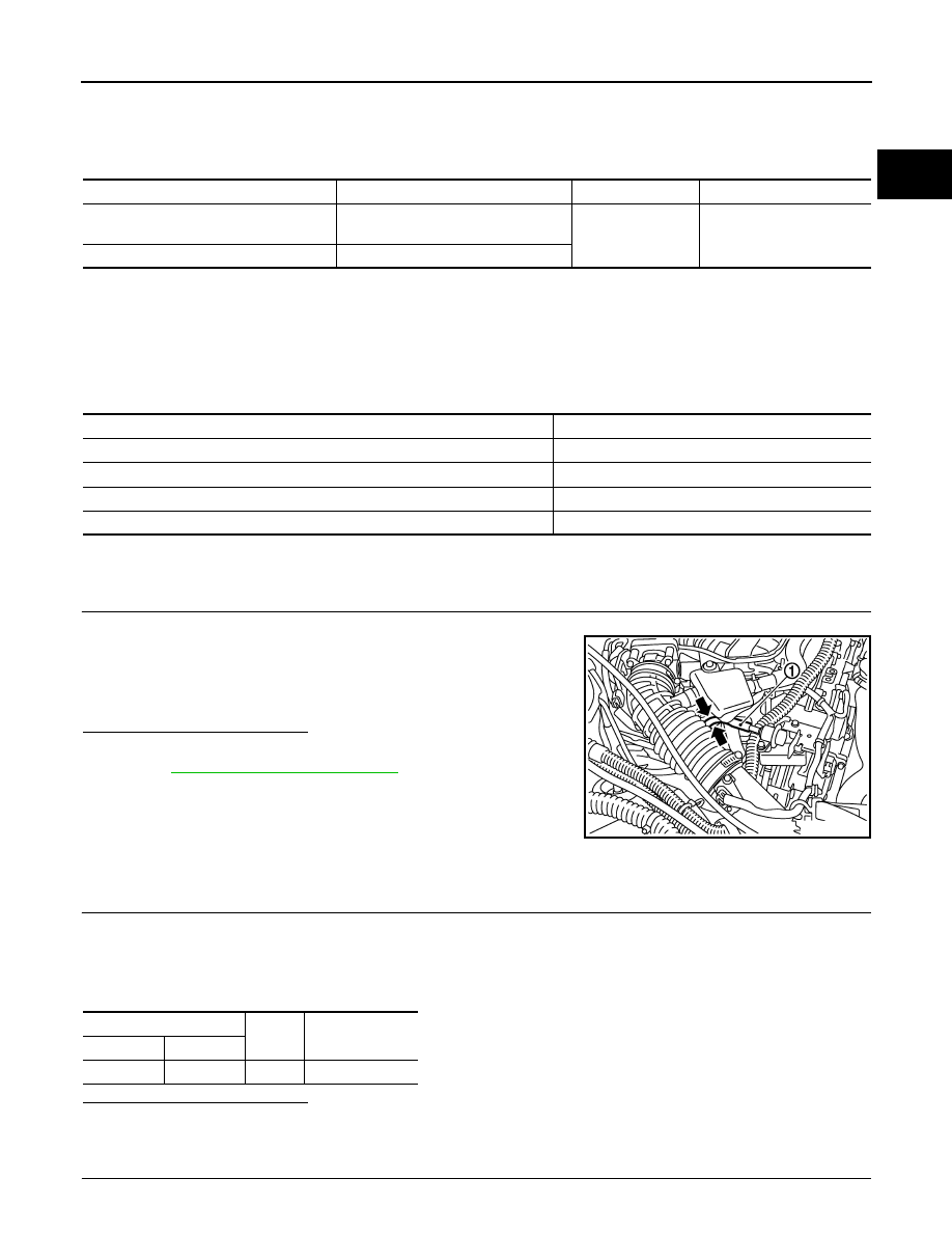
CHECK FUEL PUMP FUNCTION
1.
Turn ignition switch ON.
2.
Pinch fuel feed hose (1) with two fingers.
Is the inspection result normal?
YES
>> INSPECTION END
NO
>>
.
Diagnosis Procedure
INFOID:0000000005237090
1.
CHECK FUEL PUMP POWER SUPPLY CIRCUIT-I
1.
Turn ignition switch OFF.
2.
Disconnect ECM harness connector.
3.
Turn ignition switch ON.
4.
Check the voltage between ECM harness connector and ground.
Is the inspection result normal?
YES
>> GO TO 4.
NO
>> GO TO 2.
2.
CHECK FUEL PUMP POWER SUPPLY CIRCUIT-II
Sensor
Input signal to ECM
ECM Function
Actuator
Crankshaft position sensor
Camshaft position sensor
Engine speed*
Fuel pump control
Fuel pump relay
↓
Fuel pump
Battery
Battery voltage*
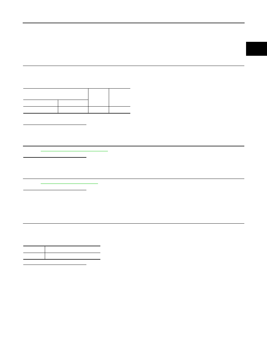
Condition
Fuel pump operation
Ignition switch is turned to ON.
Operates for 1 second.
Engine running and cranking
Operates.
When engine is stopped
Stops in 1.5 seconds.
Except as shown above
Stops.
Fuel pressure pulsation should be felt on the fuel feed
hose for 1 second after ignition switch is turned ON.
JMBIA0020ZZ
ECM
Ground
Voltage
Connector
Terminal
F101
22
Ground
Battery voltage

EC-474
< DTC/CIRCUIT DIAGNOSIS >
[VQ35HR]
FUEL PUMP
Check the voltage between IPDM E/R harness connector and ground.
Is the inspection result normal?
YES
>> GO TO 3.
NO
>> GO TO 10.
3.
DETECT MALFUNCTIONING PART
Check the following.
• Harness connectors E3, F1
• Harness connectors F104, F105
• Harness for open or short between IPDM E/R and ECM
>> Repair open circuit, short to ground or short to power in harness or connectors.
4.
CHECK FUEL PUMP POWER SUPPLY CIRCUIT-II
1.
Turn ignition switch OFF.
2.
Reconnect all harness connectors disconnected.
3.
Disconnect “fuel level sensor unit and fuel pump (main)” harness connector.
4.
Turn ignition switch ON.
5.
Check the voltage between “fuel level sensor unit and fuel pump (main)” harness connector and ground.
Is the inspection result normal?
YES
>> GO TO 8.
NO
>> GO TO 5.
5.
CHECK 15 A FUSE
1.
Turn ignition switch OFF.
2.
Disconnect 15 A fuse (No. 41) from IPDM E/R.
3.
Check 15 A fuse.
Is the inspection result normal?
YES
>> GO TO 6.
NO
>> Replace 15 A fuse.
6.
CHECK FUEL PUMP POWER SUPPLY CIRCUIT-IV
1.
Disconnect IPDM E/R harness connector E5.
2.
Check the continuity between IPDM E/R harness connector and “fuel level sensor unit and fuel pump
(main)” harness connector.
3.
Also check harness for short to ground and short to power.
Is the inspection result normal?
YES
>> GO TO 10.
NO
>> GO TO 7.
7.
DETECT MALFUNCTIONING PART
IPDM E/R
Ground
Voltage
Connector
Terminal
E7
77
Ground
Battery voltage
Fuel level sensor unit and fuel pump (main)
Ground
Voltage
Connector
Terminal
B22
1
Ground
Battery voltage should exist for 1 second
after ignition switch is turned ON.
IPDM E/R
Fuel level sensor unit and fuel pump
(main)
Continuity
Connector
Terminal
Connector
Terminal
E5
13
B22
1
Existed
FUEL PUMP
EC-475
< DTC/CIRCUIT DIAGNOSIS >
[VQ35HR]
C
D
E
F
G
H
I
J
K
L
M
A
EC
N
P
O
Check the following.
• Harness connectors E121, B3
• IPDM E/R harness connector E5
• Harness for open or short between IPDM E/R and “fuel level sensor unit and fuel pump (main)”
>> Repair open circuit or short to power in harness or connectors.
8.
CHECK FUEL PUMP GROUND CIRCUIT
1.
Turn ignition switch OFF.
2.
Check the continuity between “fuel level sensor unit and fuel pump (main)” harness connector and
ground.
3.
Also check harness for short to power.
Is the inspection result normal?
YES
>> GO TO 9.
NO
>> Repair open circuit or short to power in harness or connectors.
9.
CHECK FUEL PUMP
EC-475, "Component Inspection"
Is the inspection result normal?
YES
>> GO TO 10.
NO
>> Replace fuel pump.
10.
CHECK INTERMITTENT INCIDENT
GI-36, "Intermittent Incident"
.
Is the inspection result normal?
YES
>> Replace IPDM E/R.
NO
>> Repair or replace harness or connectors.
Component Inspection
INFOID:0000000005237091
1.
CHECK FUEL PUMP
1.
Turn ignition switch OFF.
2.
Disconnect “fuel level sensor unit and fuel pump (main)” harness connector.
3.
Check resistance between “fuel level sensor unit and fuel pump” terminals as follows.
Is the inspection result normal?
YES
>> INSPECTION END
NO
>> Replace “fuel level sensor unit and fuel pump”
Fuel level sensor unit and fuel pump
(main)
Ground
Continuity
Connector
Terminal
B22
3
Ground
Existed
Terminals
Resistance
1 and 3
0.2 - 5.0
Ω
[at 25
°
C (77
°
F)]

EC-476
< DTC/CIRCUIT DIAGNOSIS >
[VQ35HR]
ICC BRAKE SWITCH
ICC BRAKE SWITCH
Description
INFOID:0000000005237092
When the brake pedal is depressed, ICC brake switch is turned OFF and stop lamp switch is turned ON. ECM
detects the state of the brake pedal by those two types of input (ON/OFF signal).
Refer to
for the ICC function.
Component Function Check
INFOID:0000000005237093
1.
CHECK ICC BRAKE SWITCH FUNCTION
With CONSULT-III
1.
Turn ignition switch ON.
2.
Select “BRAKE SW1” in “DATA MONITOR” mode with CONSULT-III.
3.
Check “BRAKE SW1” indication under the following conditions.
Without CONSULT-III
1.
Turn ignition switch ON.
2.
Check the voltage between ECM harness connector terminals as follows.
Is the inspection result normal?
YES
>> INSPECTION END
NO
>> Go to
Diagnosis Procedure
INFOID:0000000005237094
1.
CHECK DTC WITH ICC SENSOR INTEGRATED UNIT
CCS-44, "Diagnosis Description"
Are any DTCs detected?
YES
>> Perform the Diagnosis Procedure corresponding to the detected DTC.
NO
>> GO TO 2.
2.
CHECK OVERALL FUNCTION
With CONSULT-III
1.
Turn ignition switch ON.
2.
Select “BRAKE SW1” in “DATA MONITOR” mode with CONSULT-III.
3.
Check “BRAKE SW1” indication under the following conditions.
Without CONSULT-III
1.
Turn ignition switch ON.
2.
Check the voltage between ECM harness connector terminals under the following conditions.
Monitor item
Condition
Indication
BRAKE SW1
(ICC brake switch)
Brake pedal
Slightly depressed
OFF
Fully released
ON
ECM
Condition
Voltage (V)
Connector
+
–
Terminal
Terminal
M107
126
(ICC brake switch signal)
128
Brake pedal
Slightly depressed
Approx. 0
Fully released
Battery voltage
Monitor item
Condition
Indication
BRAKE SW1
(ICC brake switch)
Brake pedal
Slightly depressed
OFF
Fully released
ON
Нет комментариевНе стесняйтесь поделиться с нами вашим ценным мнением.
Текст