Infiniti FX35, FX50 (S51). Manual — part 956
EM-124
< UNIT DISASSEMBLY AND ASSEMBLY >
[VQ35HR]
CYLINDER BLOCK
• Check the piston ring side clearance. Refer to
.
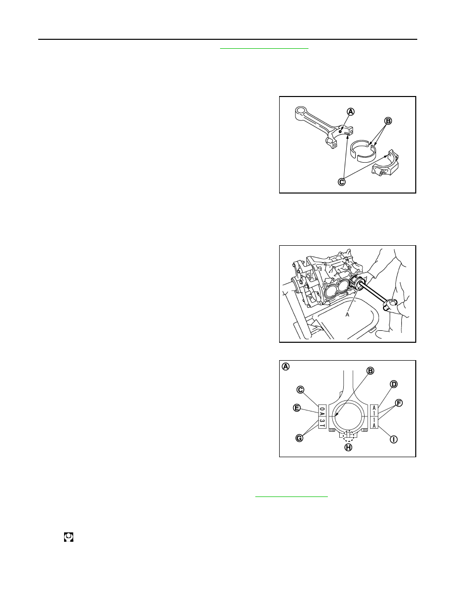
11. Install connecting rod bearings to connecting rod and connecting rod bearing cap.
CAUTION:
Be careful not to drop connecting rod bearing, and to scratch the surface.
• Before installing connecting rod bearings, apply engine oil to the bearing surface (inside). Do not apply
engine oil to the back surface, but thoroughly clean it.
• When installing, align connecting rod bearing stopper protru-
sion (B) with cutout (C) of connecting rods and connecting rod
bearing caps to install.
• Ensure the oil hole (A) on connecting rod and that on the cor-
responding bearing are aligned.
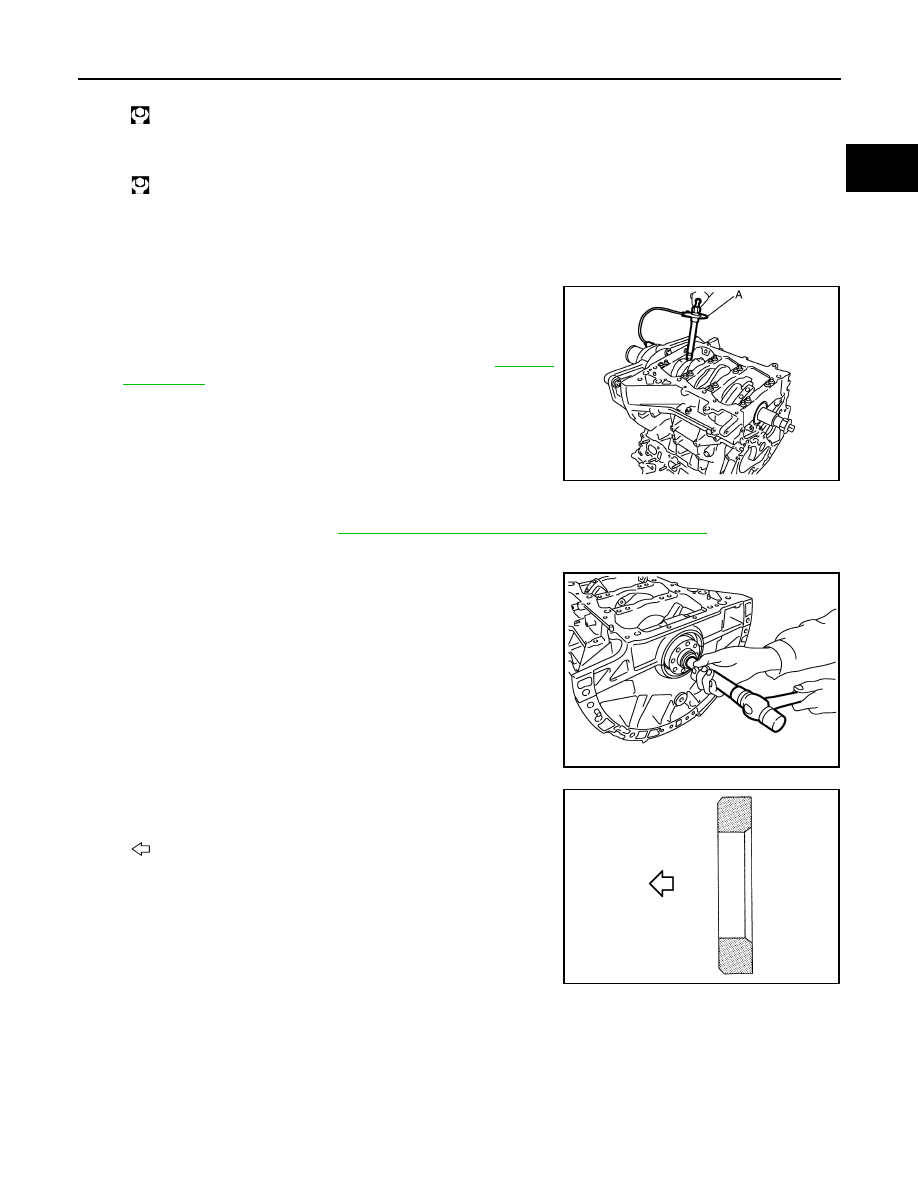
12. Install piston and connecting rod assembly to crankshaft.
• Position crankshaft pin corresponding to connecting rod to be installed onto the bottom dead center.
• Apply engine oil sufficiently to the cylinder bore, piston and crankshaft pin journal.
• Match the cylinder position with the cylinder number on connecting rod to install.
• Be sure that front mark on piston crown is facing front of engine.
• Using a piston ring compressor [SST: EM03470000 (J-8037)]
(A) or suitable tool, install piston with the front mark on the pis-
ton crown facing the front of the engine.
CAUTION:
Be careful not to damage the cylinder wall and crankshaft
pin, resulting from an interference of the connecting rod big
end.
13. Install connecting rod bearing cap.
• Match the stamped cylinder number marks on connecting rod
with those on connecting rod bearing cap to install.
• Be sure that front mark (H) on connecting rod bearing cap is facing front of the engine.
14. Tighten connecting rod bolt as per the following:
a.
Inspect the outer diameter of connecting rod bolt. Refer to
.
b.
Apply engine oil to the threads and seats of connecting rod bolts.
c.
Tighten connecting rod bolts.
d.
Completely loosen connecting rod bolts.
JPBIA0206ZZ
JPBIA0207ZZ
A
: Sample codes
B
: Bearing stopper groove
C
: Small-end diameter grade
D
: Big-end diameter grade
E
: Weight grade
F
: Cylinder No.
G
: Management code
I
: Management code
: 28.4 N·m (2.9 kg-m, 21 ft-lb)
JPBIA0208ZZ
CYLINDER BLOCK
EM-125
< UNIT DISASSEMBLY AND ASSEMBLY >
[VQ35HR]
C
D
E
F
G
H
I
J
K
L
M
A
EM
N
P
O
e.
Tighten connecting rod bolts.
f.
Tighten connecting rod bolts (clockwise).
CAUTION:
Always use the angle wrench [SST: KV10112100 (BT8653-
A)] (A). Never tightening based on visual check alone.
• After tightening connecting rod bolts, check that crankshaft
rotates smoothly.
• Check the connecting rod side clearance. Refer to
.
15. Install baffle plate.
16. Install new rear oil seal. Refer to
EM-80, "REAR OIL SEAL : Removal and Installation"
.
• Apply new engine oil to both oil seal lip and dust seal lip.
17. Install pilot converter.
• With a drift of the following outer diameter, press-fit as far as it
will go.
• Press-fit pilot converter with its chamfer facing crankshaft as
shown in the figure.
: 0 N·m (0 kg-m, 0 ft-lb)
: 24.5 N·m (2.5 kg-m, 18 ft-lb)
Angle tightening: 90 degrees
JPBIA0209ZZ
Pilot converter
: Approximately 33 mm (1.30 in)
PBIC2947E
: Crankshaft side
JPBIA0210ZZ
EM-126
< UNIT DISASSEMBLY AND ASSEMBLY >
[VQ35HR]
CYLINDER BLOCK
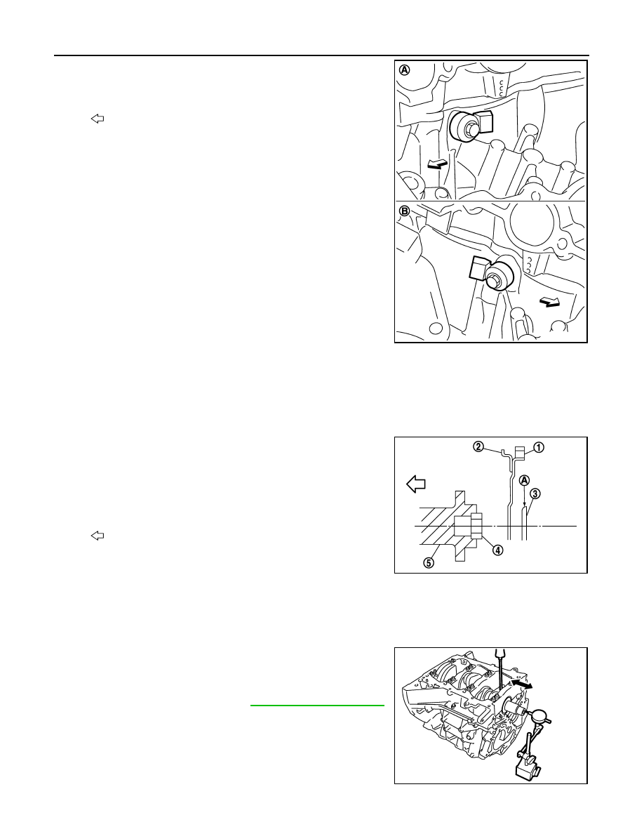
18. Install knock sensors.
• Install knock sensor so that connector faces rear of the
engine.
• After installing knock sensor, connect harness connector, and
lay it out to rear of the engine.
CAUTION:
• Never tighten mounting bolts while holding connector.
• If any impact by dropping is applied to knock sensor,
replace it with new one.
NOTE:
• Check that there is no foreign material on the cylinder block
mating surface and the back surface of knock sensor.
• Check that knock sensor does not interfere with other parts.
19. Note the following item, assemble in the reverse order of disassembly after this step.
Drive plate
• When installing drive plate to crankshaft, be sure to correctly align crankshaft side dowel pin and drive
plate side dowel pin hole.
CAUTION:
If these are not aligned correctly, engine runs roughly and “MIL” turns on.
• Install drive plate (2) and reinforcement plate (3) as shown in
the figure.
• Holding ring gear with the ring gear stopper [SST:
KV10118600 (J-48641)].
• Tighten the mounting bolts crosswise over several times.
Inspection
INFOID:0000000005245178
CRANKSHAFT END PLAY
• Measure the clearance between thrust bearings and crankshaft
arm when crankshaft is moved fully forward or backward with a dial
indicator.
• If the measured value exceeds the limit, replace thrust bearings,
and measure again. If it still exceeds the limit, replace crankshaft
also.
CONNECTING ROD SIDE CLEARANCE
A
: Bank 1
B
: Bank 2
: Engine front
JPBIA0211ZZ
1
: Ring gear
4
: Pilot converter
5
: Crankshaft
A
: Rounded
: Engine front
JPBIA0212ZZ
Standard and limit
: Refer to
.
PBIC2953E

CYLINDER BLOCK
EM-127
< UNIT DISASSEMBLY AND ASSEMBLY >
[VQ35HR]
C
D
E
F
G
H
I
J
K
L
M
A
EM
N
P
O
• Measure the side clearance between connecting rod and crank-
shaft arm with a feeler gauge.
• If the measured value exceeds the limit, replace connecting rod,
and measure again. If it still exceeds the limit, replace crankshaft
also.
PISTON TO PISTON PIN OIL CLEARANCE
Piston Pin Hole Diameter
Measure the inner diameter of piston pin hole with an inside
micrometer (A).
Piston Pin Outer Diameter
Measure the outer diameter of piston pin with a micrometer (A).
Piston to Piston Pin Oil Clearance
(Piston to piston pin oil clearance) = (Piston pin hole diameter) – (Piston pin outer diameter)
• If the calculated value is out of the standard, replace piston and piston pin assembly.
• When replacing piston and piston pin assembly, refer to
.
NOTE:
• Piston is available together with piston pin as assembly.
• Piston pin (piston pin hole) grade is provided only for the parts installed at the plant. For service parts, no
piston pin grades can be selected. (Only “0” grade is available.)
PISTON RING SIDE CLEARANCE
Standard and limit
: Refer to
PBIC2954E
Standard
: Refer to
JPBIA0217ZZ
Standard
: Refer to
JPBIA0218ZZ
Standard
: Refer to
Нет комментариевНе стесняйтесь поделиться с нами вашим ценным мнением.
Текст