Infiniti FX35, FX50 (S51). Manual — part 955

EM-120
< UNIT DISASSEMBLY AND ASSEMBLY >
[VQ35HR]
CYLINDER BLOCK
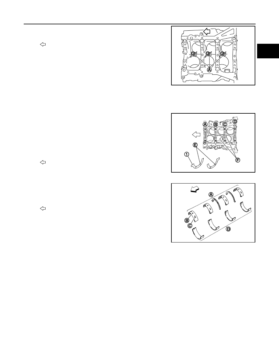
Screw M8 bolt [pitch: 1.25 mm (0.0492 in) length: approximately
50 mm (1.97 in)] into bolt holes (A). Then equally tighten each
bolt, and remove lower cylinder block.
CAUTION:
• Be careful not to damage the mounting surfaces.
• Never tighten bolts too much.
• Never insert screw driver, this will damage the mating sur-
face.
10. Remove crankshaft.
11. Pull rear oil seal out from rear end of crankshaft.
12. Remove main bearings and thrust bearings from cylinder block and lower cylinder block.
CAUTION:
• Be careful not to drop main bearing, and to scratch the surface.
• Identify installation positions, and store them without mixing them up.
13. Remove oil jet.
ASSEMBLY
1.
Fully air-blow engine coolant and engine oil passages in cylinder block, cylinder bore and crankcase to
remove any foreign material.
CAUTION:
Use a goggles to protect your eye.
2.
Install each plug to cylinder block as shown in the figure.
• Apply sealant to the thread of water drain plugs (1), (4).
Use Genuine RTV Silicone Sealant or an equivalent. Refer
to
GI-16, "Recommended Chemical Products and Seal-
.
• Apply sealant to the thread of plugs.
Use Genuine high strength thread locking sealant or an
equivalent. Refer to
• Replace washers (2) with new one.
• Tighten each plug as specified below.
3.
Install oil jet.
: Engine front
JPBIA0414ZZ
3
: Plug
: Engine front
JPBIA0191ZZ
Part
Washer
Tightening torque
1
No
19.6 N·m (2.0 kg-m, 14 ft-lb)
3
Yes
78.0 N·m (8.0 kg-m, 58 ft-lb)
4
Yes
12.3 N·m (1.3 kg-m, 9 ft-lb)
CYLINDER BLOCK
EM-121
< UNIT DISASSEMBLY AND ASSEMBLY >
[VQ35HR]
C
D
E
F
G
H
I
J
K
L
M
A
EM
N
P
O
• Insert oil jet dowel pin (A) into cylinder block dowel pin hole,
and tighten mounting bolts.
4.
Install main bearings and thrust bearings as per the following:
CAUTION:
Be careful not to drop main bearing, and to scratch the surface.
a.
Remove dust, dirt, and engine oil on bearing mating surfaces of cylinder block and lower cylinder block.
b.
Install thrust bearings (1) to the both sides of the No. 3 journal
housing on cylinder block.
• Install thrust bearings with the oil groove (E) facing crankshaft
arm (outside).
c.
Install main bearings paying attention to the direction.
• Main bearing with oil hole (B) and groove (C) goes on cylinder
block. The one without them goes on lower cylinder block.
• Before installing main bearings, apply engine oil to the bearing
surface (inside). Do not apply engine oil to the back surface,
but thoroughly clean it.
• When installing, align main bearing stopper protrusion to cut-
out of cylinder block and lower cylinder block.
• Ensure the oil holes on cylinder block and those on the corresponding bearing are aligned.
5.
Install crankshaft to cylinder block.
• While turning crankshaft by hand, check that it turns smoothly.
6.
Install lower cylinder block.
NOTE:
Lower cylinder block cannot be replaced as a single part, because it is machined together with cylinder
block.
: Engine front
JPBIA0198ZZ
A
: No. 1
B
: No. 2
C
: No. 3
D
: No. 4
F
: Thrust bearing installation position
: Engine front
JPBIA0199ZZ
A
: Cylinder block side
D
: Lower cylinder block side
: Engine front
JPBIA0200ZZ
EM-122
< UNIT DISASSEMBLY AND ASSEMBLY >
[VQ35HR]
CYLINDER BLOCK
• Apply a continuous bead of liquid gasket with the tube presser
(commercial service tool) to lower cylinder block as shown in
the figure.
Use Genuine RTV Silicone Sealant or an equivalent. Refer
to
GI-16, "Recommended Chemical Products and Sealants"
7.
Inspect the outer diameter of lower cylinder block bolt. Refer to
.
8.
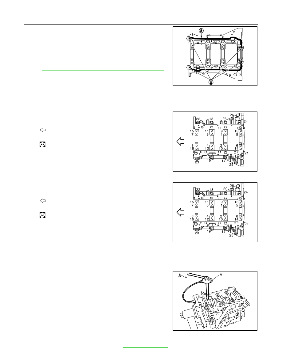
Install lower cylinder block bolts in numerical order as shown in the figure as per the following:
a.
Apply new engine oil to threads and seat surfaces of lower cylinder block bolts.
b.
Tighten lower cylinder block bolts (No. 17 to 26) in numerical
order as shown in the figure.
c.
Repeat step b.
d.
Tighten lower cylinder block bolt (No. 1 to 16) in numerical order
as shown in the figure.
e.
Tighten lower cylinder block bolt No. 1 to 16 (clockwise).
CAUTION:
Use the angle wrench [SST: KV10112100 (BT8653-A)] (A) to
check tightening angle. Never make judgment by visual
inspection.
• After installing lower cylinder block bolts, check that crankshaft can be rotated smoothly by hand.
• Check the crankshaft end play. Refer to
B
: Apply to end
a
:
φ
4.0 - 5.0 mm (0.157 - 0.197 in)
JPBIA1354ZZ
: Engine front
: 25.0 N·m (2.6 kg-m, 18 ft-lb)
JPBIA0197ZZ
: Engine front
: 35.3 N·m (3.6 kg-m, 26 ft-lb)
JPBIA0197ZZ
Angle tightening: 90 degrees
JPBIA0202ZZ
CYLINDER BLOCK
EM-123
< UNIT DISASSEMBLY AND ASSEMBLY >
[VQ35HR]
C
D
E
F
G
H
I
J
K
L
M
A
EM
N
P
O
9.
Install piston to connecting rod as per the following:
a.
Using a snap ring pliers, install new snap ring to the groove of piston rear side.
• Insert it fully into groove to install.
b.
Install piston to connecting rod.
• Using an industrial use drier or similar tool, heat piston until piston pin can be pushed in by hand without
excess force [approximately 60 to 70
°
C (140 to 158
°
F)]. From the front to the rear, insert piston pin into
piston and connecting rod.
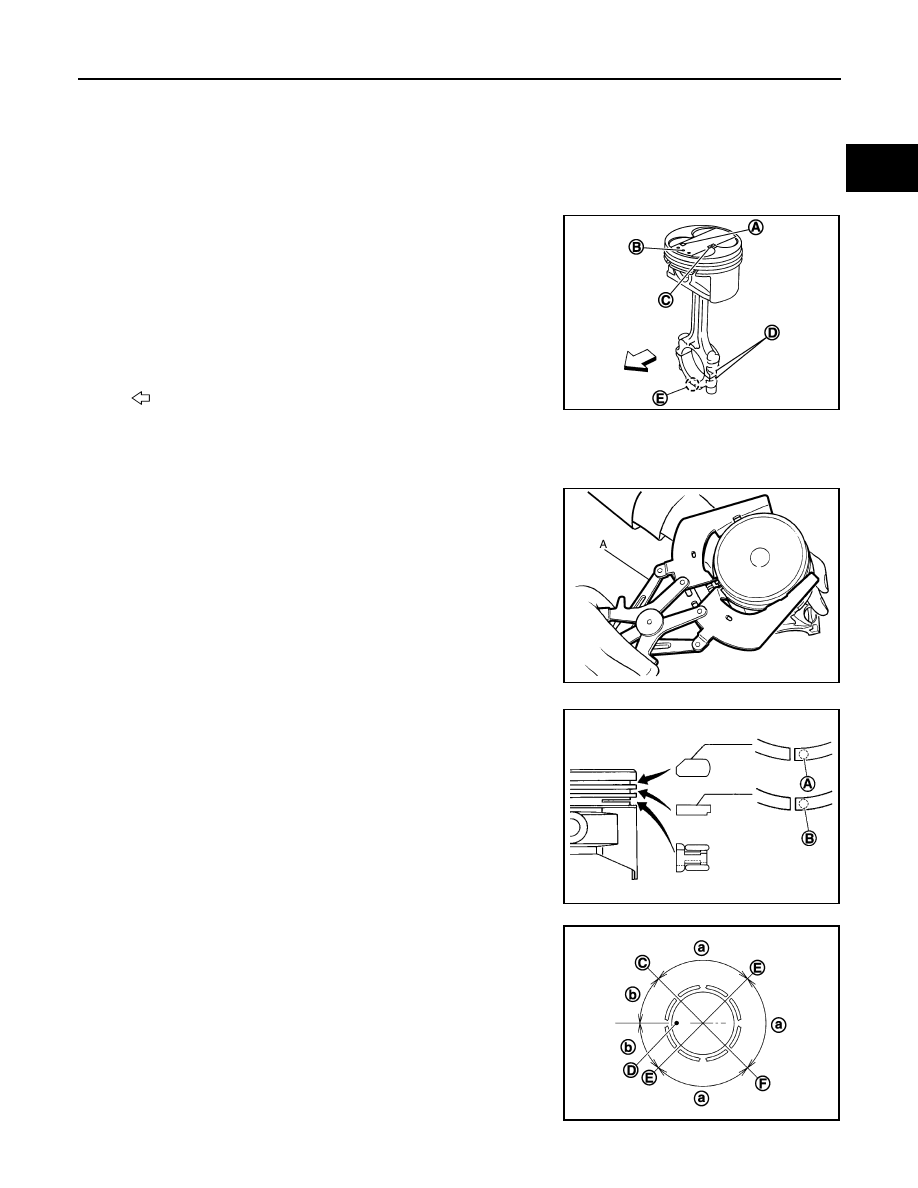
• Assemble so that the front mark on the piston head and the
cylinder number on connecting rod are positioned as shown in
the figure.
c.
Install new snap ring to the groove of the piston front side.
• Insert it fully into groove to install.
• After installing, check that connecting rod moves smoothly.
10. Using a piston ring expander (commercial service tool) (A),
install piston rings.
CAUTION:
• When installing piston rings, be careful not to damage
piston.
• Be careful not to damage piston rings by expending them
excessively.
• If there is stamped mark on ring, mount it with marked side up.
• Position each ring with the gap as shown in the figure referring
to the piston front mark (D).
A
: Piston grade number
B
: Front mark
C
: Pin grade number
D
: Cylinder number
E
: Front mark
: Engine front
JPBIA0203ZZ
JPBIA0194ZZ
Stamped mark:
Top ring (A)
: 1 N
Second ring (B)
: 2 N
JPBIA1720ZZ
C
: Top ring gap
E
: Oil ring upper or lower rail gap (either of them)
F
: Second ring and oil ring spacer gap
a
: 90 degrees
b
: 45 degrees
JPBIA0205ZZ
Нет комментариевНе стесняйтесь поделиться с нами вашим ценным мнением.
Текст