Infiniti FX35, FX50 (S51). Manual — part 954
EM-116
< UNIT DISASSEMBLY AND ASSEMBLY >
[VQ35HR]
CYLINDER HEAD
- Start engine. With engine speed increased, check again for fuel leakage at connection points.
• Run engine to check for unusual noise and vibration.
• Warm up engine thoroughly to check there is no leakage of fuel, exhaust gases, or any oil/fluids including
engine oil and engine coolant.
• Bleed air from lines and hoses of applicable lines, such as in cooling system.
• After cooling down engine, again check oil/fluid levels including engine oil and engine coolant. Refill to the
specified level, if necessary.
Summary of the inspection items:
*: Transmission/transaxle/CVT fluid, power steering fluid, brake fluid, etc.
Items
Before starting engine
Engine running
After engine stopped
Engine coolant
Level
Leakage
Level
Engine oil
Level
Leakage
Level
Other oils and fluid*
Level
Leakage
Level
Fuel
Leakage
Leakage
Leakage
Exhaust gases
—
Leakage
—
CYLINDER BLOCK
EM-117
< UNIT DISASSEMBLY AND ASSEMBLY >
[VQ35HR]
C
D
E
F
G
H
I
J
K
L
M
A
EM
N
P
O
CYLINDER BLOCK
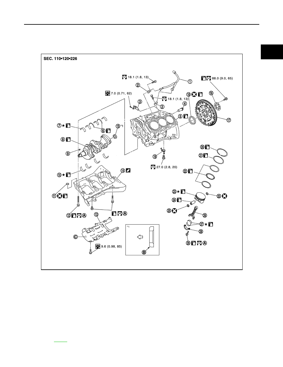
Exploded View
INFOID:0000000005245176
1.
Sub harness
2.
Knock sensor
3.
Crankshaft position sensor
4.
Cylinder block heater (for Canada)
5.
Cylinder block
6.
Thrust bearing
7.
Main bearing (upper)
8.
Crankshaft
9.
Crankshaft key
10. Main bearing (lower)
11. O-ring
12. Lower cylinder block bolt
13. Baffle plate
14. Lower cylinder block
15. Pilot converter
16. Reinforcement plate
17. Drive plate
18. Rear oil seal
19. Oil jet
20. Top ring
21. Second ring
22. Oil ring
23. Piston
24. Piston pin
25. Snap ring
26. Connecting rod
27. Connecting rod bearing
28. Connecting rod bearing cap
29. Connecting rod bolt
A.
Refer to
B.
Chamfered
C.
Front mark
JPBIA1827GB
EM-118
< UNIT DISASSEMBLY AND ASSEMBLY >
[VQ35HR]
CYLINDER BLOCK
Disassembly and Assembly
INFOID:0000000005245177
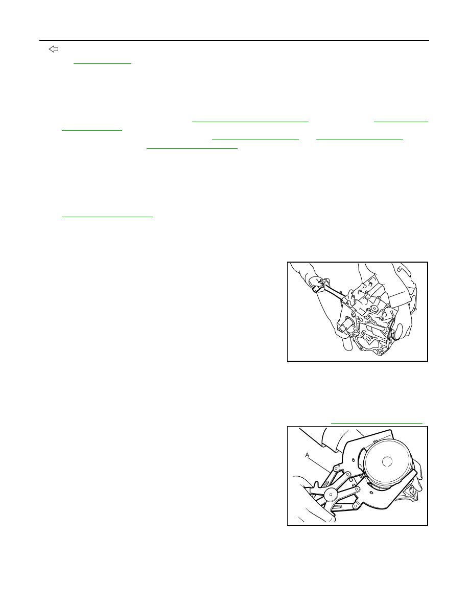
DISASSEMBLY
1.
Remove the following parts:
• Oil pans (lower and upper): Refer to
(AWD models).
• Front and rear timing chain case: Refer to
.
• Cylinder head: Refer to
2.
Remove knock sensor.
CAUTION:
Carefully handle sensor avoiding shocks.
3.
Remove baffle plate from lower cylinder block.
4.
Remove piston and connecting rod assembly with the following procedure:
• Before removing piston and connecting rod assembly, check the connecting rod side clearance. Refer to
.
CAUTION:
Be careful not to drop connecting rod bearing, and to scratch the surface.
a.
Position crankshaft pin corresponding to connecting rod to be removed onto the bottom dead center.
b.
Remove connecting rod bearing cap.
c.
Using a hammer handle or similar tool, push piston and connect-
ing rod assembly out to the cylinder head side.
CAUTION:
Be careful not to damage the cylinder wall and crankshaft
pin, resulting from an interference of the connecting rod big
end.
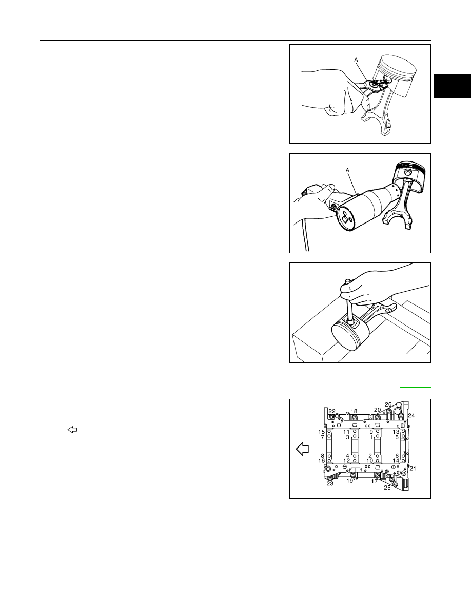
5.
Remove connecting rod bearings from connecting rod and connecting rod bearing cap.
CAUTION:
• Be careful not to drop connecting rod bearing, and to scratch the surface.
• Identify installation positions, and store them without mixing them up.
6.
Remove piston rings from piston.
• Before removing piston rings, check the piston ring side clearance. Refer to
• Use a piston ring expander (commercial service tool) (A).
CAUTION:
• When removing piston rings, be careful not to damage
piston.
• Be careful not to damage piston rings by expanding them
excessively.
7.
Remove piston from connecting rod as per the following:
: Crankshaft side
for symbols in the figure.
PBIC2940E
JPBIA0194ZZ
CYLINDER BLOCK
EM-119
< UNIT DISASSEMBLY AND ASSEMBLY >
[VQ35HR]
C
D
E
F
G
H
I
J
K
L
M
A
EM
N
P
O
a.
Using a snap ring pliers (A), remove snap rings.
b.
Heat piston to 60 to 70
°
C (140 to 158
°
F) with an industrial use
drier (A) or an equivalent.
c.
Push out piston pin with stick of outer diameter approximately 20
mm (0.79 in).
8.
Remove lower cylinder block bolts.
• Before loosening lower cylinder block bolts, measure the crankshaft end play. Refer to
• Loosen lower cylinder block bolts in the reverse order shown
in the figure in several different steps.
9.
Remove lower cylinder block as per the following:
JPBIA0195ZZ
JPBIA0196ZZ
PBIC0262E
: Engine front
JPBIA0197ZZ
Нет комментариевНе стесняйтесь поделиться с нами вашим ценным мнением.
Текст