Infiniti FX35, FX50 (S51). Manual — part 1839
A/T FLUID COOLER
TM-163
< PERIODIC MAINTENANCE >
[7AT: RE7R01A (VQ35HR)]
C
E
F
G
H
I
J
K
L
M
A
B
TM
N
O
P
A/T FLUID COOLER
Cleaning
INFOID:0000000005250147
Whenever an A/T is replaced, the A/T fluid cooler mounted in the radiator must be inspected and cleaned.
Metal debris and friction material, if present, can become trapped in the A/T fluid cooler. This debris can con-
taminate the newly serviced A/T or, in severe cases, can block or restrict the flow of ATF. In either case, mal-
function of the newly serviced A/T may result.
Debris, if present, may build up as ATF enters the cooler inlet. It will be necessary to back flush the cooler
through the cooler outlet in order to flush out any built up debris.
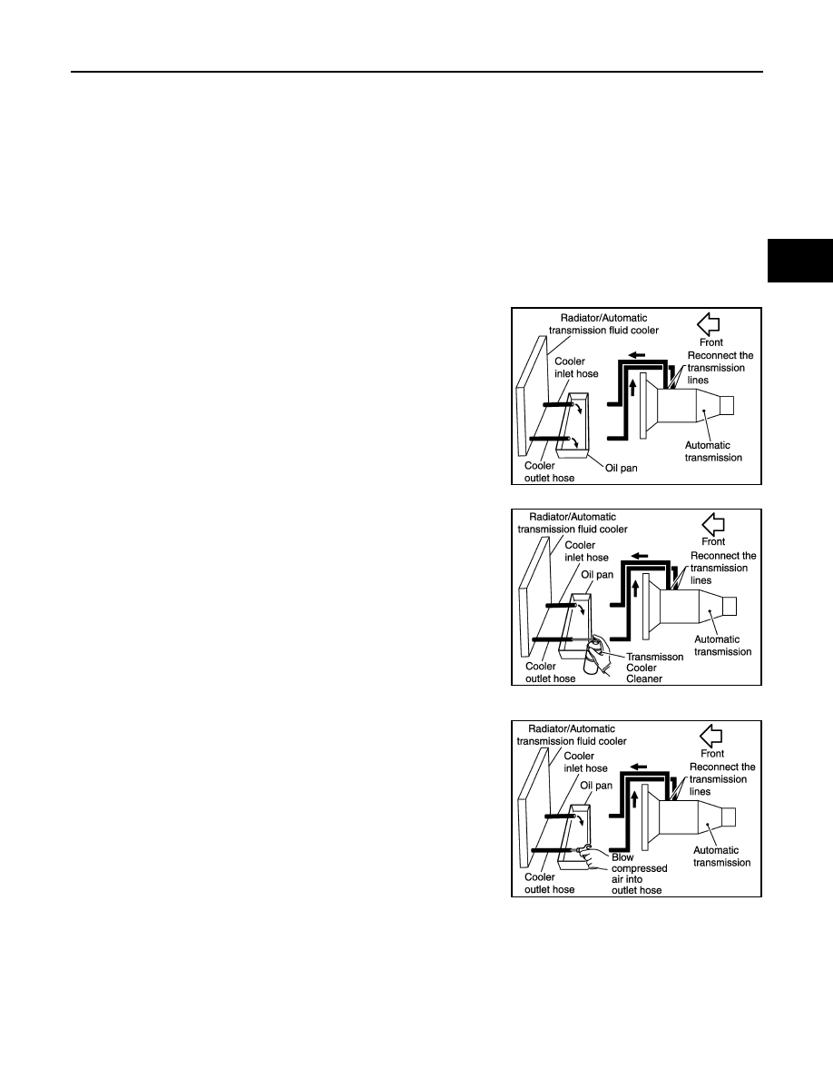
CLEANING PROCEDURE
1.
Position an oil pan under the A/T inlet and outlet cooler hoses.
2.
Identify the inlet and outlet fluid cooler hoses.
3.
Disconnect the A/T fluid cooler inlet and outlet rubber hoses
from the steel cooler tubes or by-pass valve.
NOTE:
Replace the cooler hoses if rubber material from the hose
remains on the tube fitting.
4.
Allow any ATF that remains in the cooler hoses to drain into the
oil pan.
5.
Insert the extension adapter hose of a can of Transmission
Cooler Cleaner (Nissan P/N 999MP-AM006) into the cooler out-
let hose.
CAUTION:
• Wear safety glasses and rubber gloves when spraying the
Transmission Cooler Cleaner.
• Spray Transmission Cooler Cleaner only with adequate
ventilation.
• Avoid contact with eyes and skin.
• Never breath vapors or spray mist.
6.
Hold the hose and can as high as possible and spray Transmis-
sion Cooler Cleaner in a continuous stream into the cooler outlet
hose until ATF flows out of the cooler inlet hose for 5 seconds.
7.
Insert the tip of an air gun into the end of the cooler outlet hose.
8.
Wrap a shop rag around the air gun tip and of the cooler outlet
hose.
9.
Blow compressed air regulated to 5 to 9 kg/cm
2
(71 to 128 psi)
through the cooler outlet hose for 10 seconds to force out any
remaining ATF.
10. Repeat steps 5 through 9 three additional times.
11. Position an oil pan under the banjo bolts that connect the A/T
fluid cooler steel lines to the A/T.
12. Remove the banjo bolts.
13. Flush each steel line from the cooler side back toward the A/T
by spraying Transmission Cooler Cleaner in a continuous stream for 5 seconds.
14. Blow compressed air regulated to 5 to 9 kg/cm
2
(71 to 128 psi) through each steel line from the cooler
side back toward the A/T for 10 seconds to force out any remaining ATF.
15. Ensure all debris is removed from the steel cooler lines.
16. Ensure all debris is removed from the banjo bolts and fittings.
17. Perform “DIAGNOSIS PROCEDURE”.
JPDIA0711GB
JPDIA0712GB
JPDIA0713GB
TM-164
< PERIODIC MAINTENANCE >
[7AT: RE7R01A (VQ35HR)]
A/T FLUID COOLER
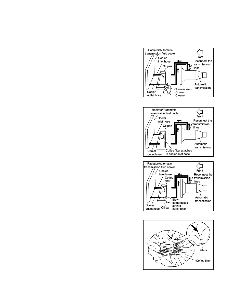
DIAGNOSIS PROCEDURE
NOTE:
Insufficient cleaning of the cooler inlet hose exterior may lead to inaccurate debris identification.
1.
Position an oil pan under the A/T inlet and outlet cooler hoses.
2.
Clean the exterior and tip of the cooler inlet hose.
3.
Insert the extension adapter hose of a can of Transmission
Cooler Cleaner (Nissan P/N 999MP-AM006) into the cooler out-
let hose.
CAUTION:
• Wear safety glasses and rubber gloves when spraying the
Transmission Cooler Cleaner.
• Spray Transmission Cooler Cleaner only with adequate
ventilation.
• Avoid contact with eyes and skin.
• Never breath vapors or spray mist.
4.
Hold the hose and can as high as possible and spray Transmis-
sion Cooler Cleaner in a continuous stream into the cooler outlet
hose until ATF flows out of the cooler inlet hose for 5 seconds.
5.
Tie a common white, basket-type coffee filter to the end of the
cooler inlet hose.
6.
Insert the tip of an air gun into the end of the cooler outlet hose.
7.
Wrap a shop rag around the air gun tip and end of cooler outlet
hose.
8.
Blow compressed air regulated to 5 to 9 kg/cm
2
(71 to 128 psi)
through the cooler outlet hose to force any remaining ATF into
the coffee filter.
9.
Remove the coffee filter from the end of the cooler inlet hose.
10. Perform “INSPECTION PROCEDURE”.
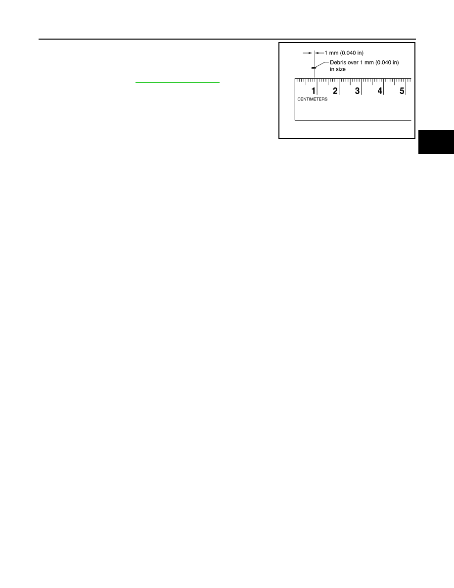
INSPECTION PROCEDURE
1.
Inspect the coffee filter for debris.
a.
If small metal debris less than 1 mm (0.040 in) in size or metal
powder is found in the coffee filter, this is normal. If normal
debris is found, the A/T fluid cooler/radiator can be re-used and
the procedure is ended.
JPDIA0712GB
JPDIA0714GB
JPDIA0715GB
SCIA2967E
A/T FLUID COOLER
TM-165
< PERIODIC MAINTENANCE >
[7AT: RE7R01A (VQ35HR)]
C
E
F
G
H
I
J
K
L
M
A
B
TM
N
O
P
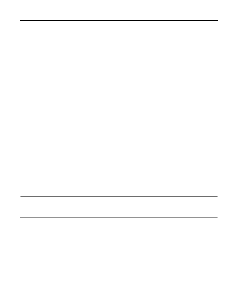
b.
If one or more pieces of debris are found that are over 1 mm
(0.040 in) in size and/or peeled clutch facing material is found in
the coffee filter, the A/T fluid cooler is not serviceable. The A/T
fluid cooler/radiator must be replaced and the inspection proce-
dure is ended. Refer to
Inspection
INFOID:0000000005250148
After performing all procedures, ensure that all remaining oil is cleaned from all components.
SCIA7031E
TM-166
< PERIODIC MAINTENANCE >
[7AT: RE7R01A (VQ35HR)]
STALL TEST
STALL TEST
Inspection and Judgment
INFOID:0000000005250149
INSPECTION
1.
Inspect the amount of engine oil. Replenish the engine oil if necessary.
2.
Drive for about 10 minutes to warm up the vehicle so that the A/T fluid temperature is 50 to 80
°
C (122 to
176
°
F). Inspect the amount of ATF. Replenish if necessary.
3.
Securely engage the parking brake so that the tires do not turn.
4.
Start the engine, apply foot brake, and place selector lever in “D” position.
5.
Gradually press down the accelerator pedal while holding down the foot brake.
6.
Quickly read off the stall speed, and then quickly release the accelerator pedal.
CAUTION:
Never hold down the accelerator pedal for more than 5 seconds during this test.
7.
Shift the selector lever to “N” position.
8.
Cool down the ATF.
CAUTION:
Run the engine at idle for at least 1 minute.
9.
Repeat steps 5 through 8 with selector lever in “R” position.
JUDGMENT OF STALL TEST
O: Stall speed within standard value position
H: Stall speed higher than standard value
L: Stall speed lower than standard value
Stall test standard value position
Stall speed
: Refer to
Selector lever position
Possible location of malfunction
“D” and “M”
“R”
Stall speed
H
O
• Low brake
• 1st one-way clutch
• 2nd one-way clutch
O
H
• Reverse brake
• 1st one-way clutch
• 2nd one-way clutch
L
L
• Engine and torque converter one-way clutch
H
H
• Line pressure low
Does not shift-up “D” or “M” position 1
→
2
Slipping in 2GR, 3GR 4GR or 6GR
2346 brake slippage
Does not shift-up “D” or “M” position 2
→
3
Slipping in 3GR, 4GR or 5GR
Direct clutch slippage
Does not shift-up “D” or “M” position 3
→
4
Slipping in 4GR, 5GR, 6GR or 7GR
High and low reverse clutch slippage
Does not shift-up “D” or “M” position 4
→
5
Slipping in 5GR, 6GR or 7GR
Input clutch slippage
Does not shift-up “D” or “M” position 5
→
6
Slipping in 2GR, 3GR, 4GR or 6GR
2346 brake slippage
Does not shift-up “D” or “M” position 6
→
7
Slipping in 7GR
Front brake slippage
Нет комментариевНе стесняйтесь поделиться с нами вашим ценным мнением.
Текст