Infiniti FX35, FX50 (S51). Manual — part 835
P0340, P0345 CMP SENSOR
EC-881
< DTC/CIRCUIT DIAGNOSIS >
[VK50VE]
C
D
E
F
G
H
I
J
K
L
M
A
EC
N
P
O
1.
Check the continuity between CMP sensor harness connector and ECM harness connector.
2.
Also check harness for short to ground and short to power.
Is the inspection result normal?
YES
>> GO TO 11.
NO
>> Repair open circuit, short to ground or short to power in harness or connectors.
11.
CHECK CAMSHAFT POSITION SENSOR
EC-881, "Component Inspection"
Is the inspection result normal?
YES
>> GO TO 12.
NO
>> Replace malfunctioning camshaft position sensor.
12.
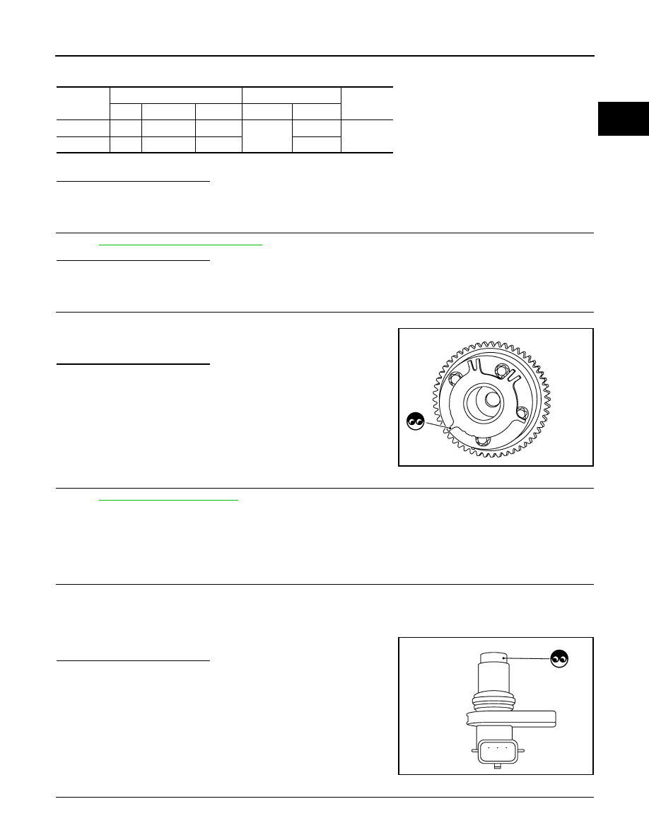
CHECK CAMSHAFT (INT)
Check the following.
• Accumulation of debris to the signal plate of camshaft front end
• Chipping signal plate of camshaft front end
Is the inspection result normal?
YES
>> GO TO 13.
NO
>> Remove debris and clean the signal plate of camshaft
front end or replace camshaft.
13.
CHECK INTERMITTENT INCIDENT
GI-36, "Intermittent Incident"
.
>> INSPECTION END
Component Inspection
INFOID:0000000005237358
1.
CHECK CAMSHAFT POSITION SENSOR-I
1.
Turn ignition switch OFF.
2.
Loosen the fixing bolt of the sensor.
3.
Disconnect camshaft position sensor harness connector.
4.
Remove the sensor.
5.
Visually check the sensor for chipping.
Is the inspection result normal?
YES
>> GO TO 2.
NO
>> Replace malfunctioning camshaft position sensor.
2.
CHECK CAMSHAFT POSITION SENSOR-II
Check resistance camshaft position sensor terminals as per the following.
DTC
CMP sensor
ECM
Continuity
Bank
Connector
Terminal
Connector
Terminal
P0340
1
F84
3
F111
59
Existed
P0345
2
F83
3
63
JMBIA0962ZZ
JMBIA0065ZZ

EC-882
< DTC/CIRCUIT DIAGNOSIS >
[VK50VE]
P0340, P0345 CMP SENSOR
Is the inspection result normal?
YES
>> INSPECTION END
NO
>> Replace malfunctioning camshaft position sensor.
Terminals (Polarity)
Resistance
1 (+) - 2 (-)
Except 0 or
∞
Ω
[at 25
°
C (77
°
F)]
1 (+) - 3 (-)
2 (+) - 3 (-)
P0420, P0430 THREE WAY CATALYST FUNCTION
EC-883
< DTC/CIRCUIT DIAGNOSIS >
[VK50VE]
C
D
E
F
G
H
I
J
K
L
M
A
EC
N
P
O
P0420, P0430 THREE WAY CATALYST FUNCTION
DTC Logic
INFOID:0000000005237359
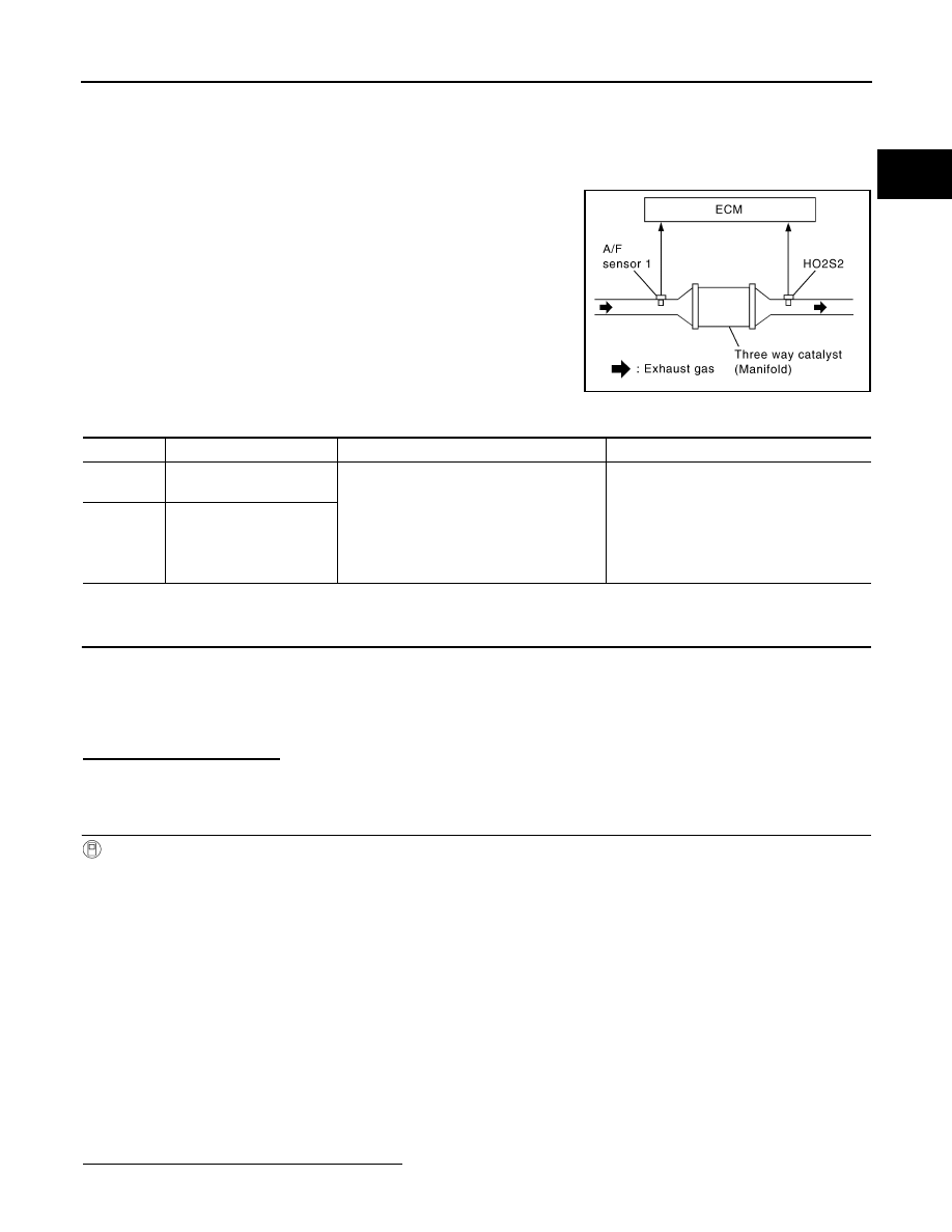
DTC DETECTION LOGIC
The ECM monitors the switching frequency ratio of air fuel ratio (A/F)
sensor 1 and heated oxygen sensor 2.
A three way catalyst (manifold) with high oxygen storage capacity
will indicate a low switching frequency of heated oxygen sensor 2.
As oxygen storage capacity decreases, the heated oxygen sensor 2
switching frequency will increase.
When the frequency ratio of A/F sensor 1 and heated oxygen sensor
2 approaches a specified limit value, the three way catalyst (mani-
fold) malfunction is diagnosed.
DTC CONFIRMATION PROCEDURE
1.
INSPECTION START
If DTC Confirmation Procedure has been previously conducted, always perform the following procedure
before conducting the next test.
1.
Turn ignition switch OFF and wait at least 10 seconds.
2.
Turn ignition switch ON.
3.
Turn ignition switch OFF and wait at least 10 seconds.
Will CONSULT-III be used?
YES
>> GO TO 2.
NO
>> GO TO 6.
2.
PERFORM DTC CONFIRMATION PROCEDURE-I
With CONSULT-III
TESTING CONDITION:
Do not maintain engine speed for more than the specified minutes below.
1.
Start engine and warm it up to the normal operating temperature.
2.
Turn ignition switch OFF and wait at least 10 seconds.
3.
Turn ignition switch ON.
4.
Turn ignition switch OFF and wait at least 10 seconds.
5.
Start engine and keep the engine speed between 3,500 and 4,000 rpm for at least 1 minute under no load.
6.
Let engine idle for 1 minute.
7.
Select “DATA MONITOR” mode with CONSULT-III.
8.
Check that “COOLAN TEMP/S” indicates more than 70
°
C (158
°
F).
If not, warm up engine and go to next step when “COOLAN TEMP/S” indication reaches to 70
°
C (158
°
F).
9.
Open engine hood.
10. Select “DTC & SRT CONFIRMATION” then “SRT WORK SUPPORT” mode with CONSULT-III.
11. Rev engine between 2,000 and 3,000 rpm and hold it for 3 consecutive minutes then release the acceler-
ator pedal completely.
12. Check the indication of “CATALYST”.
Which is displayed on CONSULT-III screen?
CMPLT >> GO TO 5.
PBIB2055E
DTC No.
Trouble diagnosis name
DTC detecting condition
Possible cause
P0420
Catalyst system efficiency
below threshold (bank 1)
• Three way catalyst (manifold) does not
operate properly.
• Three way catalyst (manifold) does not
have enough oxygen storage capacity.
• Three way catalyst (manifold)
• Exhaust tube
• Intake air leakage
• Fuel injector
• Fuel injector leakage
• Spark plug
• Improper ignition timing
P0430
Catalyst system efficiency
below threshold (bank 2)

EC-884
< DTC/CIRCUIT DIAGNOSIS >
[VK50VE]
P0420, P0430 THREE WAY CATALYST FUNCTION
INCMP >> GO TO 3.
3.
PERFORM DTC CONFIRMATION PROCEDURE-II
1.
Wait 5 seconds at idle.
2.
Rev engine between 2,000 and 3,000 rpm and maintain it until “INCMP” of “CATALYST” changes to
“CMPLT” (It will take approximately 5 minutes).
Does the indication change to “CMPLT”?
YES
>> GO TO 5.
NO
>> GO TO 4.
4.
PERFORM DTC CONFIRMATION PROCEDURE AGAIN
1.
Stop engine and cool it down to less than 70
°
C (158
°
F).
2.
Perform DTC CONFIRMATION PROCEDURE again.
>> GO TO 2.
5.
PERFORM DTC CONFIRMATION PROCEDURE-III
Check 1st trip DTC.
Is 1st trip DTC detected?
YES
>> Go to
NO
>> INSPECTION END
6.
PERFORM COMPONENT FUNCTION CHECK
With GST
Perform component function check. Refer to
EC-884, "Component Function Check"
NOTE:
Use component function check to check the overall function of the three way catalyst (manifold). During this
check, a 1st trip DTC might not be confirmed.
Is the inspection result normal?
YES
>> INSPECTION END
NO
>> Go to
Component Function Check
INFOID:0000000005237360
1.
PERFORM COMPONENT FUNCTION CHECK
With GST
1.
Start engine and warm it up to the normal operating temperature.
2.
Turn ignition switch OFF and wait at least 10 seconds.
3.
Start engine and keep the engine speed between 3,500 and 4,000 rpm for at least 1 minute under no load.
4.
Let engine idle for 1 minute.
5.
Open engine hood.
6.
Check the voltage between ECM harness connector terminals under the following conditions.
Is the inspection result normal?
YES
>> INSPECTION END
NO
>> Go to
DTC
ECM
Condition
Voltage
Connector
+
–
Terminal
Terminal
P0420
F110
32
[HO2S2
(bank 1)]
31
Keeping engine speed at 2,500 rpm
constant under no load
The voltage fluctuation cycle takes more
than 5 seconds.
• 1 cycle: 0.6 - 1.0
→
0 - 0.3
→
0.6 - 1.0
P0430
36
[HO2S2
(bank 2)]
Нет комментариевНе стесняйтесь поделиться с нами вашим ценным мнением.
Текст