Infiniti FX35, FX50 (S51). Manual — part 834
P0340, P0345 CMP SENSOR
EC-877
< DTC/CIRCUIT DIAGNOSIS >
[VK50VE]
C
D
E
F
G
H
I
J
K
L
M
A
EC
N
P
O
P0340, P0345 CMP SENSOR
Description
INFOID:0000000005237355
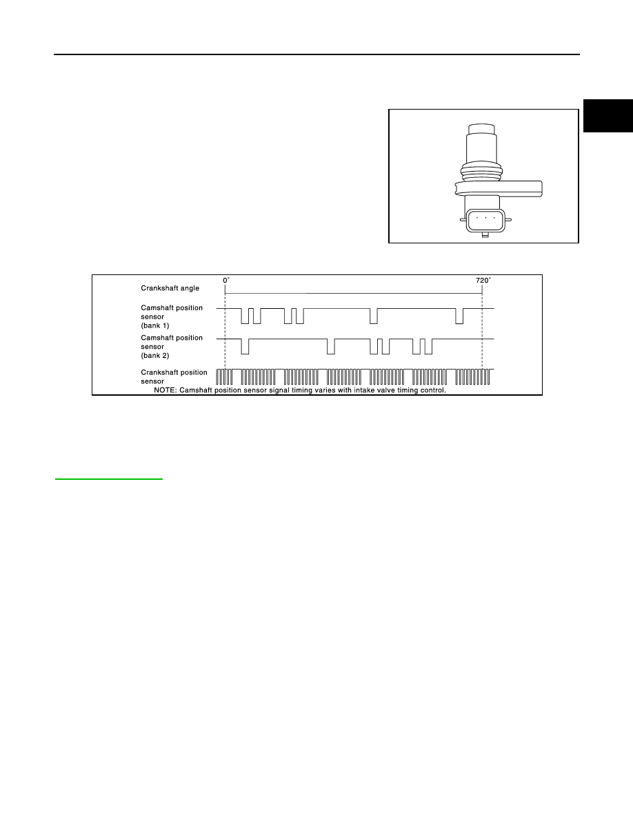
The camshaft position sensor senses the protrution of the signal
plate installed to the camshaft (INT) front end to identify a particular
cylinder. The camshaft position sensor senses the piston position.
When the crankshaft position sensor system becomes inoperative,
the camshaft position sensor provides various controls of engine
parts instead, utilizing timing of cylinder identification signals.
The sensor consists of a permanent magnet and Hall IC.
When engine is running, the high and low parts of the teeth cause
the gap with the sensor to change.
The changing gap causes the magnetic field near the sensor to
change.
Due to the changing magnetic field, the voltage from the sensor
changes.
ECM receives the signals as shown in the figure.
DTC Logic
INFOID:0000000005237356
DTC DETECTION LOGIC
NOTE:
If DTC P0345 is displayed with DTC P0643, first perform the trouble diagnosis for DTC P0643. Refer to
JMBIA0064ZZ
JMBIA1559GB

EC-878
< DTC/CIRCUIT DIAGNOSIS >
[VK50VE]
P0340, P0345 CMP SENSOR
DTC CONFIRMATION PROCEDURE
1.
PRECONDITIONING
If DTC Confirmation Procedure has been previously conducted, always perform the following procedure
before conducting the next test.
1.
Turn ignition switch OFF and wait at least 10 seconds.
2.
Turn ignition switch ON.
3.
Turn ignition switch OFF and wait at least 10 seconds.
TESTING CONDITION:
Before performing the following procedure, confirm that battery voltage is more than 10.5 V with igni-
tion switch ON.
>> GO TO 2.
2.
PERFORM DTC CONFIRMATION PROCEDURE-I
1.
Start engine and let it idle for at least 5 seconds.
If engine does not start, crank engine for at least 2 seconds.
2.
Check 1st trip DTC.
Is 1st trip DTC detected?
YES
>> Go to
NO
>> GO TO 3.
3.
PERFORM DTC CONFIRMATION PROCEDURE-I
1.
Maintain engine speed at more than 800 rpm for at least 5 seconds.
2.
Check 1st trip DTC.
Is 1st trip DTC detected?
YES
>> Go to
DTC No.
Trouble diagnosis name
DTC detecting condition
Possible cause
P0340
Camshaft position sen-
sor (bank 1) circuit
• The cylinder No. signal is not sent to ECM
for the first few seconds during engine
cranking.
• The cylinder No. signal is not sent to ECM
during engine running.
• The cylinder No. signal is not in the normal
pattern during engine running.
• Harness or connectors
[Camshaft position sensor (bank 1) circuit is
open or shorted.]
(APP sensor 2 circuit is shorted.)
(Battery current sensor circuit is shorted.)
[Crankshaft position sensor circuit is shorted.]
(EVAP control system pressure sensor circuit
is shorted.)
[Exhaust valve timing control position sensor
(bank 1) circuit is shorted.]
(Manifold absolute pressure sensor circuit is
shorted.)
• Camshaft position sensor (bank 1)
• Accelerator pedal position sensor
• Battery current sensor
• Crankshaft position sensor
• EVAP control system pressure sensor
• Exhaust valve timing control position sensor
(bank 1)
• Manifold absolute pressure sensor
• Camshaft (INT)
• Starter motor
• Starting system circuit
• Dead (Weak) battery
P0345
Camshaft position sen-
sor (bank 2) circuit
• Harness or connectors
[Camshaft position sensor (bank 2) circuit is
open or shorted.]
• Camshaft position sensor (bank 2)
• Camshaft (INT)
• Starter motor
• Starting system circuit
• Dead (Weak) battery

P0340, P0345 CMP SENSOR
EC-879
< DTC/CIRCUIT DIAGNOSIS >
[VK50VE]
C
D
E
F
G
H
I
J
K
L
M
A
EC
N
P
O
NO
>> INSPECTION END
Diagnosis Procedure
INFOID:0000000005237357
1.
CHECK STARTING SYSTEM
Turn ignition switch to START position.
Does the engine turn over? Does the starter motor operate?
YES
>> GO TO 2.
NO
>> Check starting system. (Refer to
2.
CHECK GROUND CONNECTION
1.
Turn ignition switch OFF.
2.
Check ground connections M95, F33 and F34. Refer to Ground Inspection in
.
Is the inspection result normal?
YES
>> GO TO 3.
NO
>> Repair or replace ground connection.
3.
CHECK CAMSHAFT POSITION SENSOR POWER SUPPLY CIRCUIT-I
1.
Disconnect camshaft position (CMP) sensor harness connector.
2.
Turn ignition switch ON.
3.
Check the voltage between CMP sensor harness connector and ground.
Is the inspection result normal?
YES
>> GO TO 9.
NO-1
>> P0340: GO TO 4.
NO-2
>> P0345: Repair open circuit, short to ground or short to power in harness or connectors.
4.
CHECK CMP SENSOR POWER SUPPLY CIRCUIT-II
1.
Turn ignition switch OFF.
2.
Disconnect ECM harness connector.
3.
Check the continuity between CMP sensor harness connector and ECM harness connector.
Is the inspection result normal?
YES
>> GO TO 5.
NO
>> Repair open circuit.
5.
CHECK SENSOR POWER SUPPLY CIRCUIT
Check harness for short to power and short to ground, between the following terminals.
DTC
CMP sensor
Ground
Voltage (V)
Bank
Connector
Terminal
P0340
1
F84
1
Ground
Approx. 5
P0345
2
F83
1
CMP sensor
ECM
Continuity
Bank
Connector
Terminal
Connector
Terminal
1
F84
1
F111
91
Existed

EC-880
< DTC/CIRCUIT DIAGNOSIS >
[VK50VE]
P0340, P0345 CMP SENSOR
Is the inspection result normal?
YES
>> GO TO 6.
NO
>> Repair short to ground or short to power in harness or connectors.
6.
CHECK COMPONENTS
Check the following.
• Battery current sensor (Refer to
EC-1025, "Component Inspection"
.)
• Crankshaft position sensor (Refer to
EC-876, "Component Inspection"
• EVAP control system pressure sensor (Refer to
EC-917, "Component Inspection"
.)
• Exhaust valve timing control position sensor (bank 1) (Refer to
EC-978, "Component Inspection"
.)
• Manifold absolute pressure sensor (Refer to
EC-785, "Component Inspection"
Is the inspection result normal?
YES
>> GO TO 7.
NO
>> Replace malfunctioning component.
7.
CHECK APP SENSOR
EC-1081, "Component Inspection"
.
Is the inspection result normal?
YES
>> GO TO 13.
NO
>> GO TO 8.
8.
REPLACE ACCELERATOR PEDAL ASSEMBLY
1.
Replace accelerator pedal assembly.
2.
EC-1082, "Special Repair Requirement"
.
>> INSPECTION END
9.
CHECK CMP SENSOR GROUND CIRCUIT FOR OPEN AND SHORT
1.
Turn ignition switch OFF.
2.
Disconnect ECM harness connector.
3.
Check the continuity between CMP sensor harness connector and ECM harness connector.
4.
Also check harness for short to ground and short to power.
Is the inspection result normal?
YES
>> GO TO 10.
NO
>> Repair open circuit, short to ground or short to power in harness or connectors.
10.
CHECK CMP SENSOR INPUT SIGNAL CIRCUIT FOR OPEN AND SHORT
ECM
Sensor
Connector
Terminal
Name
Connector
Terminal
F111
87
Crankshaft position sensor
F2
1
91
CMP sensor (bank 1)
F84
1
EVT control position sensor (bank 1)
F59
1
95
Battery current sensor
E21
1
EVAP control system pressure sensor
B252
3
Manifold absolute pressure sensor
F65
1
M160
99
APP sensor 2 (Without ICC)
E112
6
APP sensor 2 (With ICC)
E116
3
DTC
CMP sensor
ECM
Continuity
Bank
Connector
Terminal
Connector
Terminal
P0340
1
F84
2
F111
58
Existed
P0345
2
F83
2
62
Нет комментариевНе стесняйтесь поделиться с нами вашим ценным мнением.
Текст