Infiniti FX35, FX50 (S51). Manual — part 592
SIDE OIL SEAL
DLN-203
< REMOVAL AND INSTALLATION >
[REAR FINAL DRIVE: R200]
C
E
F
G
H
I
J
K
L
M
A
B
DLN
N
O
P
SIDE OIL SEAL
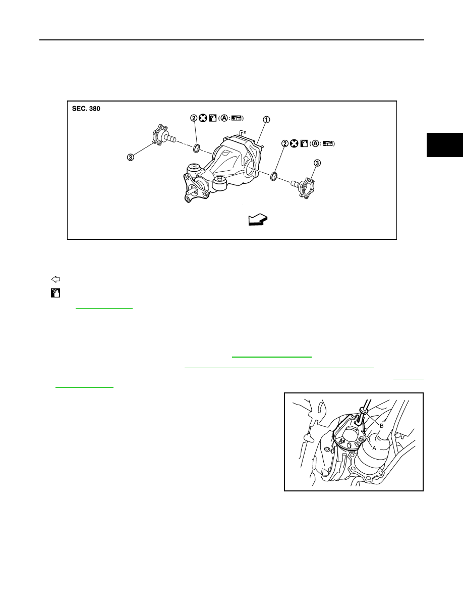
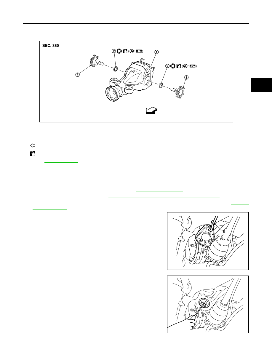
2WD
2WD : Exploded View
INFOID:0000000005249229
2WD : Removal and Installation
INFOID:0000000005249230
REMOVAL
1.
Remove center muffler with a power tool. Refer to
2.
Remove rear wheel sensor. Refer to
BRC-132, "REAR WHEEL SENSOR : Exploded View"
.
3.
Remove drive shaft from final drive with a power tool. Then suspend it by wire, etc. Refer to
4.
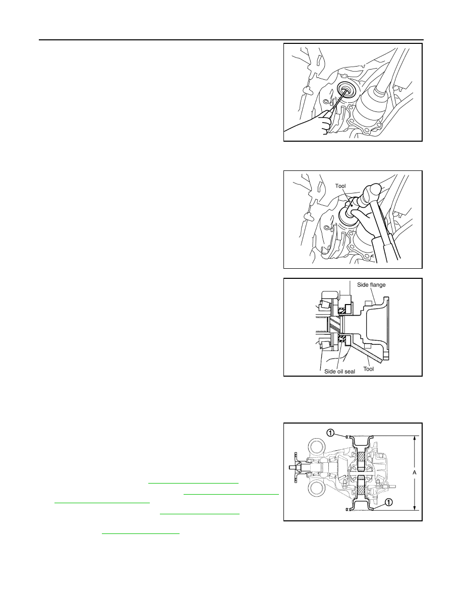
Install attachment (A) [SST: KV40104100 (
—
)] to side
flange, and then pull out the side flange with the sliding hammer
(B) [SST: ST36230000 (J-25840-A)].
NOTE:
Circular clip installation position: Final drive side
1.
Final drive assembly
2.
Side oil seal
3.
Side flange
A.
Oil seal lip
: Vehicle front
: Apply gear oil.
Refer to
for symbols not described above.
JPDID0233ZZ
JSDIA0105ZZ
DLN-204
< REMOVAL AND INSTALLATION >
[REAR FINAL DRIVE: R200]
SIDE OIL SEAL
5.
Remove side oil seal, using a flat-bladed screwdriver.
CAUTION:
Never damage gear carrier.
INSTALLATION
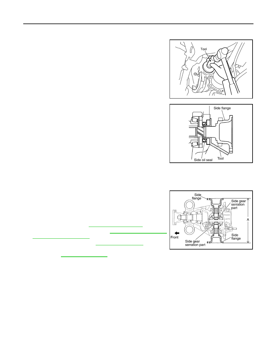
1.
Apply multi-purpose grease to side oil seal lips.
2.
Install side oil seal until it becomes flush with the case end,
using the drift [SST: KV38100200 (J-26233)].
CAUTION:
• Never reuse oil seal.
• When installing, never incline oil seal.
3.
Install side flange with the following procedure.
a.
Attach the protector [SST: KV38107900 (J-39352)] to side oil
seal.
b.
After the side flange is inserted and the serrated part of side
gear has engaged the serrated part of flange, remove the pro-
tector.
c.
Put a suitable drift on the center of side flange, then drive it until sound changes.
NOTE:
When installation is completed, driving sound of the side flange turns into a sound that seems to affect the
whole final drive.
d.
Confirm that the dimension of the side flange (1) installation
measurement (A) in the figure comes into the following.
4.
Install drive shaft. Refer to
5.
Install rear wheel sensor. Refer to
6.
Install center muffler. Refer to
.
7.
When oil leaks while removing, check oil level after the installa-
tion. Refer to
.
AWD
SDIA1584E
SDIA1585E
SDIA0822E
Standard
A
: 326 – 328 mm (12.83 – 12.91 in)
JSDIA0106ZZ
SIDE OIL SEAL
DLN-205
< REMOVAL AND INSTALLATION >
[REAR FINAL DRIVE: R200]
C
E
F
G
H
I
J
K
L
M
A
B
DLN
N
O
P
AWD : Exploded View
INFOID:0000000005249231
AWD : Removal and Installation
INFOID:0000000005249232
REMOVAL
1.
Remove center muffler with a power tool. Refer to
2.
Remove rear wheel sensor. Refer to
BRC-132, "REAR WHEEL SENSOR : Exploded View"
.
3.
Remove drive shaft from final drive with a power tool. Then suspend it by wire, etc. Refer to
4.
Install attachment (A) [SST: KV40104100 (
—
)] to side
flange, and then pull out the side flange with the sliding hammer
(B) [SST: ST36230000 (J-25840-A)].
NOTE:
Circular clip installation position: Final drive side
5.
Remove side oil seal, using a flat-bladed screwdriver.
CAUTION:
Never damage gear carrier.
1.
Final drive assembly
2.
Side oil seal
3.
Side flange
A.
Oil seal lip
: Vehicle front
: Apply gear oil.
Refer to
for symbols not described above.
JPDID0235ZZ
JSDIA0105ZZ
SDIA1584E
DLN-206
< REMOVAL AND INSTALLATION >
[REAR FINAL DRIVE: R200]
SIDE OIL SEAL
INSTALLATION
1.
Apply multi-purpose grease to side oil seal lips.
2.
Install side oil seal until it becomes flush with the case end,
using the drift [SST: KV38100200 (J-26233)].
CAUTION:
• Never reuse oil seal.
• When installing, never incline oil seal.
3.
Install side flange with the following procedure.
a.
Attach the protector [SST: KV38107900 (J-39352)] to side oil
seal.
b.
After the side flange is inserted and the serrated part of side
gear has engaged the serrated part of flange, remove the pro-
tector.
c.
Put a suitable drift on the center of side flange, then drive it until sound changes.
NOTE:
When installation is completed, driving sound of the side flange turns into a sound that seems to affect the
whole final drive.
d.
Confirm that the dimension of the side flange installation mea-
surement (A) in the figure comes into the following.
4.
Install drive shaft. Refer to
5.
Install rear wheel sensor. Refer to
6.
Install center muffler. Refer to
.
7.
When oil leaks while removing, check oil level after the installa-
tion. Refer to
.
SDIA1585E
SDIA0822E
Standard
A
: 326 – 328 mm (12.83 – 12.91 in)
SDIA1039E
Нет комментариевНе стесняйтесь поделиться с нами вашим ценным мнением.
Текст